Hi to All
I am with a question, there any way to reduce the DC offset in the differential pair? This issue is addressed in book of Douglas Self (Audio Power Amplifier Design Handbook, Third edition, PAG 85-89)
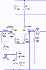
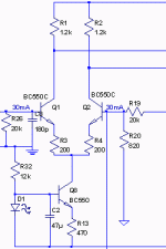
In my design amp had to use high-beta TRs in input pair, , even so, have limited input impedance in 20K and the DC offset is 32mA (Fig attached), according to what is in the book of Self, the current generates noise(blameless amp of Self, has only 10K input impedance).
PS:I do not have DC offset in output (<1mA).
Thanks
Attachments
cliff said:Is that the simulatedvalue of base current?
If so it is impossible!
Yes, must simulate funcion .OP then just put the cursor on top node, the value appears in the bottom bar of the simulator.
Yes (attached)cliff said:Is R26/R32 junction ground?
[/B]
I must mention value DC, I put in the picture as commentcliff said:Need to post some voltages and show full schematic [/B]
Attachments
You seem to have two different ground symbols! Are they connected?
I am sure your English is much better than my Portuguese, but I do not understand your words
If that is the complete schematic it cannot work.
You must have the power and feedback connected for the simulator to make sense!
I am sure your English is much better than my Portuguese, but I do not understand your words
If that is the complete schematic it cannot work.
You must have the power and feedback connected for the simulator to make sense!
Yes is connectedcliff said:You seem to have two different ground symbols! Are they connected?
cliff said:I am sure your English is much better than my Portuguese, but I do not understand your words[/B]

Can you tell me which part did not understand, would happy if you tell me
cliff said:If that is the complete schematic it cannot work. [/B]
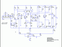
No, I put as in the book of Self, attached complete scheme..
Attachments
cliffforrest said:OK.
You probably have an error in your schematic.
Try this:
Disconnect the servo (remove the 100K resistor)
Make the input 0v, or ground it.
Measure the voltages on the input pair, E,B,C and list them here.
The schematic is correct, I measured DC Offset in other schematics, directly in the differential pair.
- But, I put the wrong value, where is 32mA should read 32mV.
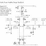
In this schematic can see the DC-offset, directly in the differential pair, the schematic is the book of the Self.
Attachments
Rafael,
IF your circuit is correct, and IF you don't have any wiring errors, then non matched transistors in the diff pair will give you a mismatch. Just throwing in two transistors with the same part number is not good enough - we use monolithic duals in our equipment to avoid this problem: MAT02 for NPN, MAT03 for PNP. They have a guaranteed 50uV and 100uV max offset!
These are metal can and out of productoion, but AD have them in plastic cases now, same chip, lower price.
Regards, Allen (Vacuum State)
- Status
- This old topic is closed. If you want to reopen this topic, contact a moderator using the "Report Post" button.
- Home
- Amplifiers
- Solid State
- DC 0ffset input pair


