I have been busy building the guitar amp which I have mentioned on these forums before.
I have a problem with hum on some of the preamplifier circuits. The background:
pre amp transformer: 9V AC, 50 VA, 230V (on 240 supply), 15% regulation (from tables).
Current drawn: 37mA.
Filter caps: 4000uF
Voltage DC: 15 V DC
Ripple current theoretical: 90mV p2p
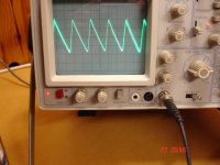
Ripple current as seen on scope : +/-40mV (totally agrees with theoretical)
Ripple current on scope with additional 4700uF: +/- 24mV
From the above it can be seen that all is normal and as expected.
Except I did all my designs using my bench power supply, which has 0 ripple. When we introduce ripple into the equation bad things happen.
I have tried adding voltage regulation in the form of a LM317 and it did reduce the ripple to half, but did not eliminate it.
Therefore I now have a PCB which houses 4 pre-amplifiers (reverb out, reverb in, mixer and headphones), all built with discrete components, of which 2 are suffering badly with hum and the other 2 are immune. All pre-amps are bypassed locally with a 100uF and a 100nF ceramic.
So it happens both the hum-affected pre-amps are a new design of mine which I have not ever used before, works perfectly with the bench power supply but fails with mains. These pre-amps use a class B push-pull at the output (to be able to drive the headphones and the reverb springs).
I have two options:
1. eliminate ripple completely (as my bench power supply does) or
2. revisit the pre-amp designs that is suffering so badly.
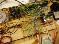
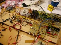
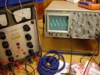
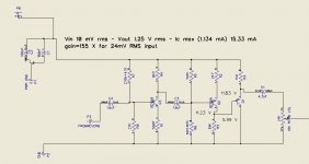
I attach the problematic circuit and some pics of the half-finished project.
Please help if you can")
I have a problem with hum on some of the preamplifier circuits. The background:
pre amp transformer: 9V AC, 50 VA, 230V (on 240 supply), 15% regulation (from tables).
Current drawn: 37mA.
Filter caps: 4000uF
Voltage DC: 15 V DC
Ripple current theoretical: 90mV p2p
Ripple current as seen on scope : +/-40mV (totally agrees with theoretical)
Ripple current on scope with additional 4700uF: +/- 24mV
From the above it can be seen that all is normal and as expected.
Except I did all my designs using my bench power supply, which has 0 ripple. When we introduce ripple into the equation bad things happen.
I have tried adding voltage regulation in the form of a LM317 and it did reduce the ripple to half, but did not eliminate it.
Therefore I now have a PCB which houses 4 pre-amplifiers (reverb out, reverb in, mixer and headphones), all built with discrete components, of which 2 are suffering badly with hum and the other 2 are immune. All pre-amps are bypassed locally with a 100uF and a 100nF ceramic.
So it happens both the hum-affected pre-amps are a new design of mine which I have not ever used before, works perfectly with the bench power supply but fails with mains. These pre-amps use a class B push-pull at the output (to be able to drive the headphones and the reverb springs).
I have two options:
1. eliminate ripple completely (as my bench power supply does) or
2. revisit the pre-amp designs that is suffering so badly.
I attach the problematic circuit and some pics of the half-finished project.
Please help if you can
Attachments
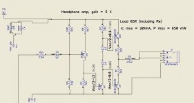
Ineterestingly this pre-amp with a huge 170x gain does not suffer from hum at all. I know the use of NPN followed by PNP amplifies hum out of phase and reduces it. Is this perhaps the way to go for the other circuit too (simply add a NPN stage at its front?)
Attachments
Hi Akis just a thought but have you tried moving the toroid further away? It may be airborne, and the new circuit may be more suceptable to this form of noise. I have that problem with the preamp in my integrated amp, picks up a lot of hum radiated by the torroid, move the torroid out of the case and it drops dramatically. I ended up putting a lead sheild over the torroid which improved things a lot.
Tony.
Tony.
Hi
I have also used an external transformer, about 3 feet away, with the two toroidals shown on the picture completely switched off. Same issue.
I have tried various combinations and the problem is caused by the ripple itself. My circuit is not designed to be immune to it.
I am in the process of adding an NPN transistor at the front with the same gain as the PNP that follows (x2), see if it will eliminate hum! Here's hoping.
Power supply ripple is eliminated by using some constant current sources in series with the supply rails. For example, you can connect a PNP transistor in common base mode in series with the positive rail comming from the smoothing caps. Connect the emitter as input and the collector as output. Connect the base via a 15-20K resistor to 0V rail. The inverse in the negative supply rail using a NPN transistor. Transistors must have a power rate according to the consumption of circuit feeded. This circuit can be used only in small power circuits. Not in power amplifiers!
Take a look in the site of Bryston which offers ready schematics of such circuits. Study the power supply schematics to get some ideas.
In power amplifiers, the ripple exists in supply rails regardless if we use monster smoothing caps. In the small signal stages of amplifier, where the problem of noise caused from ripple it is worse than the output stage, the use of constant current sources it is very common and eliminates completelly the ripple.
As for that said Greg Erskine, it is right by some way, but the existence of ripple worsen the problem of hum and buzz noise. Toroids, are :bs: by 99%. Those are apparently very well screened... ha, ha, ha! Those are in reality very nice transmission devices of strong electromagnetic flux in any direction!
You must be verry cautiouss as for their place and orientation against the pcbs of amplification. A general rule to avoid the infection of amplifiers from the straight magnetic flux transmited from the toroid, it is the place of xformer horizontal and the pcbs vertical (to form an "L" shape) or the inverse, and far away between them as possible.
The covers of the case, acts as well like mirrors and reflects in unpredictable directions the magnetic flux of toroid. In such a case, you might not have hum noise with the device oppened but when you mount the covers on the case, you might have noise! Amazing but real! Try some experiments on this.
I am tired from toroids. The best instrument to check the output noise it is a high sensitivity P.A. speaker (like a 103dB/1W) connected in output. Trust me, i have seen with my scope amplifiers with output noise of 2mVrms - which is theoretically inaudible - but the speaker connected in output reveals the very small - but audible! - buzz or hum noise exists yet.
I wish you success.
Fotios
Last edited:
thanks for all comments.
The NPN transistor in front of the PNP did not fix it but resulted in a rather messier PCB.
However I eliminated ripple completely by using a typical common collector regulator comprising of a single NPN transistor in line with the positive rail (there is no negative rail), and a zener for voltage reference at its base bypased by a capacitor. Taking the voltage reference straight from the zener into the base of the transistor halves the ripple, but this is not good enough. So I used two RC networks in series before feeding the base and there is absolutely no ripple at all any more and the hum is gone!! I wonder why the LM317 regulator I tried earlier did not achieve the same (or better) result.
It was probably a grounding problem in the first place, which went away as you modified the circuit. In any case, it's good that you found a solution. If you want an order of magnitude improvement you may want to have a look here
http://www.diyaudio.com/forums/showthread.php?t=143693
http://www.diyaudio.com/forums/showthread.php?t=143693
I wonder why the LM317 regulator I tried earlier did not achieve the same (or better) result.
Maybe because you did not used the proper bypass electrolytic caps connected accross input/output of LM317 and GND node.
In the pic is the Bryston ripple eliminating circuit that i told you. I tried it and except that is very simple, it is also very effective. The only mistake, it is the zener (1N4760 - 68V) connected between the bases of transistors in schematic, because does not offers enough bias current to make the transistors conducted, consequently there is not output voltage. By replacing the zener with a resistor between 15 to 22KΩ (22K it is prefferable because is not warmed so much like a 15K) the problem of biasing is resolved and we can get a very clean output voltage free of ripple by 90%.
Fotios
Attachments
It was probably a grounding problem in the first place, which went away as you modified the circuit. In any case, it's good that you found a solution. If you want an order of magnitude improvement you may want to have a look here
http://www.diyaudio.com/forums/showthread.php?t=143693
Indeed, it is a very inspired circuit but with a wrong title like "simplistic". With 6 BJTs and FETs and arround 8 to 10 caps-resistors-zeners included, this circuit is not so much simplistic. Instead, it is some complex. It has not to offer any practical solution to ripple noise of akis preamplifier which is oriented for musical instrument use. Instead, it is well suited for other circuits of high gain or big sensitivity which demands the zeroing of supply ripple remaining and other noises, like RIAA stages.
Please, don't missunderstand me but i wish for everyone to be very cautious in his suggestions and propositions according to the circumstance of a concrete circuit for which is asked help from any member here. I have suffered from non-related replies to my agonizing questions, enough times in the past here. Fortunatelly, i am 35 years in the round, and by 99% i find solutions in the lot of the service manuals which i have in my stock. Schematics from the service manuals of well known companies, are a priceless treasure!
Fotios
I think this is the categoric answer of what went wrong. The simple PSU intended to supply all the pre-amps in my guitar amp produces normal ripple, nothing out of the ordinary, for example as I said in the original post, ripple of 80mV p2p with a current drawn of 36 mA. The transformer / PSU can provide up to 4 A at 12 V (but is probably AC at that stage).
This normal ripple entered some of my pre-amps (not all), and created this huge hum. I tried modifying some of the pre-amps to no avail, it only made things worse and it is hard modifying on a printed PCB, makes such mess.
I did the following measurements. I tested drawing various levels of currents, up to 1.3 A, which is 25% of the rated total (of my PSU). I measured the ripple voltage right at the PSU filter. I also measured the voltage after the regulator. I also tried different regulator types, including a LM317, at various loads, from 36mA to 1.3A.
I must say here that on the scope, even at the 5mV division, it is very hard to see "trace" ripple, my ears are usually better at detecting "no ripple" than the scope. I had a pair of headphones on for that reason.
The simplest way to reduce ripple, since we are talking a few hundred mA of current at most, is a fat resistor and a capacitor after it (RC). I did some experiments and the ripple can be halved, or better, but is still there, and my pre-amp faithfully amplifies what is there it.
I also tried the common base transistor at the rail line suggestion, it did not achieve much.
I then tried two separate LM317s on different boards and the result was the same, very bad regulation and half the ripple through (with another shape, very assymetrical, but ripple never the less). I have no idea what's wrong with the LM317, perhaps that is how it works, I tried adding various capacitors at its adjustment pin, before, and after, no luck, the ripple remains.
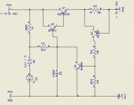
I finally tried the a combination of the RC circuit and zener/diode regulation amplification. That seemed to work wonders. The final diagram is below. The sries voltage sense and associated circuitry is for shorts protection and may add some modicum of ripple reduction too.
I also added a 12V 12 cm fan and its noise is also completely eliminated , even though it draws a hefty 80mA and not only increases ripple dramatically at the PSU, it also introduces its own noise while spinning. The fan was added at the PSU, BEFORE the regulator.
I cannot remember what current I tested it for, the combination of R2/C5 is used to eliminate ripple at the chosen current. I used my ears for that measurement because everything was a line at the scope at that stage.
This normal ripple entered some of my pre-amps (not all), and created this huge hum. I tried modifying some of the pre-amps to no avail, it only made things worse and it is hard modifying on a printed PCB, makes such mess.
I did the following measurements. I tested drawing various levels of currents, up to 1.3 A, which is 25% of the rated total (of my PSU). I measured the ripple voltage right at the PSU filter. I also measured the voltage after the regulator. I also tried different regulator types, including a LM317, at various loads, from 36mA to 1.3A.
I must say here that on the scope, even at the 5mV division, it is very hard to see "trace" ripple, my ears are usually better at detecting "no ripple" than the scope. I had a pair of headphones on for that reason.
The simplest way to reduce ripple, since we are talking a few hundred mA of current at most, is a fat resistor and a capacitor after it (RC). I did some experiments and the ripple can be halved, or better, but is still there, and my pre-amp faithfully amplifies what is there it.
I also tried the common base transistor at the rail line suggestion, it did not achieve much.
I then tried two separate LM317s on different boards and the result was the same, very bad regulation and half the ripple through (with another shape, very assymetrical, but ripple never the less). I have no idea what's wrong with the LM317, perhaps that is how it works, I tried adding various capacitors at its adjustment pin, before, and after, no luck, the ripple remains.
I finally tried the a combination of the RC circuit and zener/diode regulation amplification. That seemed to work wonders. The final diagram is below. The sries voltage sense and associated circuitry is for shorts protection and may add some modicum of ripple reduction too.
I also added a 12V 12 cm fan and its noise is also completely eliminated , even though it draws a hefty 80mA and not only increases ripple dramatically at the PSU, it also introduces its own noise while spinning. The fan was added at the PSU, BEFORE the regulator.
I cannot remember what current I tested it for, the combination of R2/C5 is used to eliminate ripple at the chosen current. I used my ears for that measurement because everything was a line at the scope at that stage.
Attachments
Last edited:
thanks for all comments.
The NPN transistor in front of the PNP did not fix it but resulted in a rather messier PCB.
However I eliminated ripple completely by using a typical common collector regulator comprising of a single NPN transistor in line with the positive rail (there is no negative rail), and a zener for voltage reference at its base bypased by a capacitor. Taking the voltage reference straight from the zener into the base of the transistor halves the ripple, but this is not good enough. So I used two RC networks in series before feeding the base and there is absolutely no ripple at all any more and the hum is gone!! I wonder why the LM317 regulator I tried earlier did not achieve the same (or better) result.
The problem with that design is feedback through the power supply from output stages into the input stage.
I always decouple the first stage with a resistor and a large capacitor.
Akis, because i am faced 1 month ago with a similar problem like your (the only difference it is my project which is a power amplifier with +/-60V supply rails and a a gain of 41) i try to transfer in you my experience. The main problem of my project it is the noisy core of the 500VA toroid xformer. This amplifier it is no so simple, because includes balanced and single inputs and potentiometers for volume control. By some way is like an integrated amplifier. The drive boards (which are implemented with discrettes and not ICs) in which included the balanced to single converters and the volume pots, are seperated from the main amplifier boarbs. Although each one circuit it is very noiseless, when joined between them it starts the hum and buzz caused from the crackling noise of the core to heared enough loud in the output. I have redraw for second time the whole amplifier but the noise reduced only in half. After enough research i found that the pot which is connected between the output of drive board and the input of amplifier must have a value of 1,5KΩ as much. This eliminates almost completelly the noise. I use a pair of very sensitive AKG headphones to hear the noise exists. Ths moment, the buzz noise has the same level with the hiss noise (between 0,8 to 1,2 mVrms measured with the DSO), but it still exists! Of course, a so small noise is inaudible from the most senseless Hi-Fi speakers of 90dB/1W. But this issue becames an obsession for me. I have discovered as well, that the alu plates which used to join the case and those used for covers, increases the noise when are mounted on the case of amplifier. I don't know if plates (3mm thick) behaves like mirrors or conductors of electromagnetic flux. I think that are like mirrors. For this, these two days i am in drilling proccess of thousands ventilation holes in the top and bottom covers, under and over the toroid. If my assumption is correct, then the holes instead to reflect the magnetic flux, they may cause successive refractions of flux to eliminate it (like STEALTH ). I will inform you in Sunday for the result, when the drilling (with milling machine) will completted.
Fotios
). I will inform you in Sunday for the result, when the drilling (with milling machine) will completted.Fotios
Last edited:
- Status
- This old topic is closed. If you want to reopen this topic, contact a moderator using the "Report Post" button.
- Home
- Amplifiers
- Solid State
- Help with ripple