Thanks for the link to the other thread.
I did not see that one before. It sure has lots of useful info!
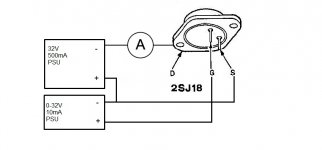
I have a 2x32V Thurlby Thandar powersupply (very good PSU, can recommend)
I set the two outputs in series and the one over drain and source to 32V 500mA
Then I measured voltage drop at VGS=0 (usually around half a volt)
Then the IDS=0 voltage, usually around 10V for good devices, 20V for chinese ones
Then IDS 40mA (just a value I thought about using for some reason) This was usually like a volt lower than the previous value.
The relevant rank number is only the last digit. The remaining two letters and one digit in the front indicate the batch, so it's a kind of date code (ascending).
The ranks are about 2.5V apart and indicate the Vgs at which Id=100mA at Vds=50V, roughly Vge = 7.5 + (2.5 * rank), this is valid for ranks 3 to 8. So, rank 3 is 12V, rank 8 is 27.5V. It should be noted that the rank number is actually a mixture of Vgs and Idss and higher Vgs is BETTER not worse, for these amps (but not necessarily for gen 2 amps like the N7 and F7).
Buying VFETs, especially 2SK60, 2SJ18 on the net is risky. Even 2SK82, 2SJ28 unless it's from Acronman elevtronics - not affiliated but I have bought from him on various occasions during the last 5 years or so and they all come from the same stock (in fact the same Nelson Pass used in the VFET anniversary amp). THey are all rank 3 (last two digits 33).
The chinese sources will send you whatever VFET and rank you want - and it will most probably BE a VFET, most probably rank 0, 1 or 2 which are actually sub-par devices (usable but not for these amps), that had the original markings stripped off and new ones stamped on. These will remove easily with alcohol, as it's just inkjet print. 2SK82 and 2SJ28 from the same sources will most likely be the same 2SK60/2SJ18 just with different print.
In other words, VFETs from china are like a box of chocolates, you never know what you're going to get

I've probably written all of this a dozen times but OK, here it is again, hopefully the search engine will find it when someone looks for it.
PS 2SJ28/2SK82 are usable in these amps but it's not trivial. It may work if you just pop them in but there are non-obvious factors that may lead to problems. TO get it working right a set of small but important mods to the driver circuit is needed, that have to do with stability (danger of oscillation!) , available bias voltage range, maximum drive current (these amps let the VFETs go into gate current), bias current vs power supply voltage compensation (unadjusted it will generate a lot more intermodulation with 100Hz/120Hz and multiples, from the ripple in the power supply).
Last edited:
Thanks ilimzn for the info!
I will try to get the amp working with single pairs of the original VFETs first and then reconsider the 28/82 and maybe try to look for more 18/60...
I found that the reason for the imbalance in VDC was the burned PA channel.
I thought it was ok except for the VFETs.
It was even playing a little with the fried VFETs and I desoldered the drivers to check them (only with a multimeter though).
The 3k3 resistors seem to have run quite hot at some point, but I measured them to be ok.
All small transistors (soldered in place) measure equal with the non-burned channel.
This is still tricky and I consider myself relatively experienced with other amps
Better get back to trying to fix the SMPS in a HK HS 300 and continue with VFET things tomorrow
I do have some schematics but what I want is the test Jig or schematic if you have, to match Vfets with common Ranks for parallel purposes.Thanks for the link to the other thread.
I did not see that one before. It sure has lots of useful info!
I have a 2x32V Thurlby Thandar powersupply (very good PSU, can recommend)
I set the two outputs in series and the one over drain and source to 32V 500mA
Then I measured voltage drop at VGS=0 (usually around half a volt)
Then the IDS=0 voltage, usually around 10V for good devices, 20V for chinese ones
Then IDS 40mA (just a value I thought about using for some reason) This was usually like a volt lower than the previous value.
From the TA-5650 schematic it was easy to figure out how the voltages should be connected.
Which schematic do you need?
The amp schematic can be found at hifiengine and other schematics I do not have.
I will sure send the one I have if you like?
I think the VFET is quite resistive between drain and source.
Someone correct me if I am wrong?
I can also test this later.
And the factory "matching" was done at 50V 100mA I hear , so I guess we should try to keep to this.
I just don't have a 50V PSU at the moment
Also 50x0.1=5W which will heat up the VFET rather quickly.
I got the damn HK HS 300 fixed so I can now get back to this "slightly finer" piece of equipment
Well,
It seems like the VDC-imbalance in my WEGA was not that serious.
I replaced the BIAS trippots with 1K ones and other resistors that looked fried (but measured ok).
I tried a pair of loosely selected J28/K82 (VGS around 15V) and got some signal out.
It was severely distorted and fault was in the preamp section, so I got the front panel loose and cleaned all moving parts and replaced all caps.
The ones in the signal path with Elna Silmic 2 and Duorex.
Ordered from China, but I kind of believe that they were genuine as wires were of copper.
Rest of the caps were replaced with Panasonic FC, and a few Elna on the power board.
Also the big caps are 6800uF Samwha, I will so replace these when I get something better!
Anyway my 16-bit FFT shows all harmonics are at least -80dB, even at zero BIAS (there must be some BIAS I think)
I set the BIAS to 30mV (60mA, or whatever it is) and started listening.
It is an awesome amp.
Actually I cannot find much wrong with the sound at all.
Still some cap mods are to come, but it is working great already!
- Status
- This old topic is closed. If you want to reopen this topic, contact a moderator using the "Report Post" button.
- Home
- Amplifiers
- Solid State
- V-fet Repair of a WEGA V4810 solid state heaven