Hey Hemuth, that looks like a job well done! I hope your amps are sounding well now... It seems they do ;-)
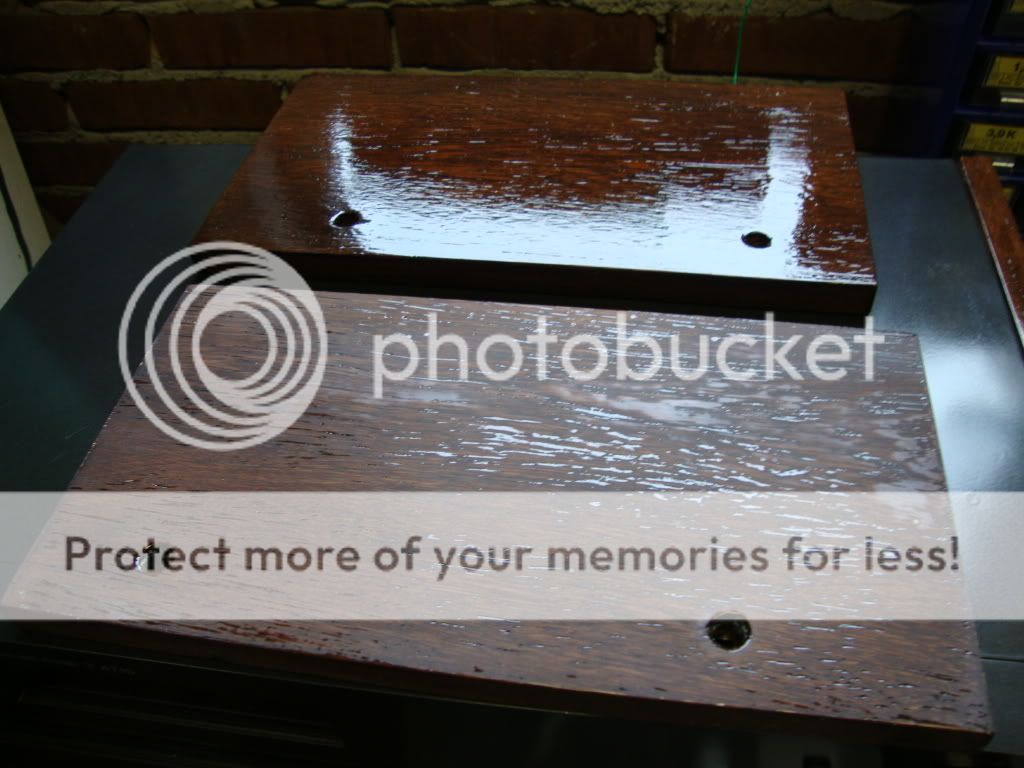
I especially like the good craftsmanship on the wooden side panels. How did you get the high gloss and keeping the dust away while the paint dries? I always get small specs of dust when trying to do a high-gloss paint job.
Hi Bouke,
How are your Passlabs amps playing?
The sound of the V-fet amp is a real exceptional nice transistor for audio, they meet most the straight amplifying characteristic of a Triode tube. And the strange thing is it really has the warm low sound of a tube amp although it has a damping factor of 40. Compared to a Mosfet the V-fet has less capacity on the gate and is there for less dependent on frequencies.
It started out to have a nice vintage set, and now I have a very rear V-fet Wega version of the rear V-fet sony TA 5650 and ST4950.
 http://www.thevintageknob.org/VFET/VFET-main.html
There are a lot of V-fet fans around but you have to be 50 years plus to have known the introduction and end of the V-fet 1974 to about 81.
It is on solid state what comes the most close to tubes.
About paint
There is always dust in the paint. I sprayed them outdoor you can spray the environment with water to prevent dust.
The real professionals sand of the last dust and bums, and after that they polish them again to get the real piano gloss finish. I tried that but did not get a good result you have to know the right tricks I guess.
Result after one can of varnish.
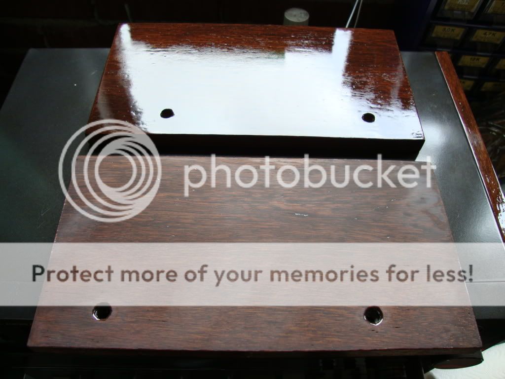
Result after sanding and second can of varnish.
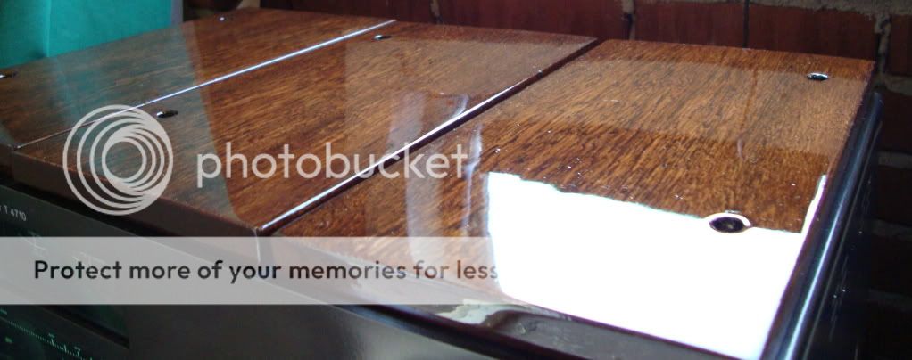
Result after sanding and third can of varnish.
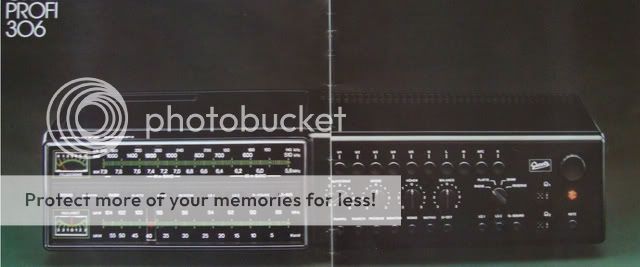
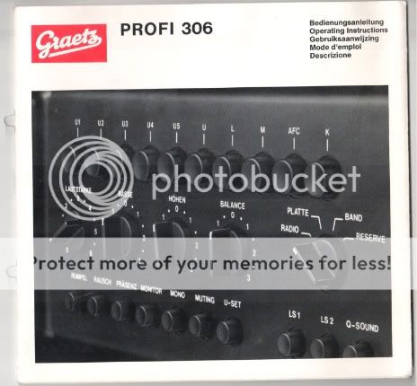
I already have a new project I managed to buy a Graetz Profi 306 (1975-1978) the receiver my father hat in the seventies and I became the audiophile-bug by it. I play it now as second set it sounds great. The electronics are very conventional and very nice build. The selector switches a dc voltage that superponates the selected input on the preampstage, so no bad audio contact!.
Regards Helmuth
Last edited:
Thanks Helmuth, very educational. I refurbished my 5650 about a year ago and now in the process to fix a 4650, with the V-Fet's from HK. I wonder if the batch numbers 53/52 won't be a problem? I assume you got the same kind of transistors as I got.
Hi Miklos,
Yes I got,
The 2SK60 are from the same ranking 52, and the
2SJ18 are from the same ranking 53 too.
Bought on ebay.
Works good on my amplifier, only there is some difference in the right channel set, the left bias was stable the right drifted more when the ballast was on for a longer time. So I would wait for more then 3 hours and check the bias again.
Cheers Helmuth
Hi Bouke,
How are your Passlabs amps playing?
(....)
Regards Helmuth
They're doing great! Fantastic powerful, rich sound. Lots of control over the bass and very good placement. have you seen the results on the final build thread?
Final pics are here: http://www.diyaudio.com/forums/showthread.php?t=137168&highlight=aleph+final+build&page=16
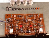
Here's a picture of the TA-4650 PA board, recaped and cleaned in the shower, with the four defective V-Fet's.
In a normal situation only one end stage is defective so all the fets defective is strange. Are sure you did the diode test? The V-fet measures short with out negative gate voltage.
@Wavebourn
It is a La Scala.
@Bouke
Good to hear your labour payed back at the end, the build looks professional perfect to the detail. When is the party to celebrate it

Regards Helmuth
Yes I did, it was a relatively cheap amp, I paid $65 on the Bay. The seller said it's needing repair, but one channel is working. It turned out non was working, for obvious reasons. Now it is not cheap anymore. I have some V-Fet experience, I fixed my 8650, 5650 and built a class A amp with the 2SK82.
http://www.diyaudio.com/forums/showthread.php?t=6338&page=21
http://www.diyaudio.com/forums/showthread.php?t=6338&page=21
Cool design that hybrid amp Miklos.Yes I did, it was a relatively cheap amp, I paid $65 on the Bay. The seller said it's needing repair, but one channel is working. It turned out non was working, for obvious reasons. Now it is not cheap anymore. I have some V-Fet experience, I fixed my 8650, 5650 and built a class A amp with the 2SK82.
http://www.diyaudio.com/forums/showthread.php?t=6338&page=21
Regards, Helmuth
Hello Helmuth, Congrats on a job well done. Boy, do those look nice!I cleaned the contacts, some remove the connector and make a sturdy wire wrap.
This is important to be sure of good contact of the +76V
I'm restoring a TA-5650 and only have +58v at the +VDC terminal on
both sides of the power board pin position #61 and #76. The !0,000uf
caps give +49 -49v. Any suggestions? It should read about 76Volts, is
that right?
 Regards,
Klipschorn dude
Hello Helmuth, Congrats on a job well done. Boy, do those look nice!
I'm restoring a TA-5650 and only have +58v at the +VDC terminal on
both sides of the power board pin position #61 and #76. The !0,000uf
caps give +49 -49v. Any suggestions? It should read about 76Volts, is
that right?
Klipschorn dude
Thanks Klipschorn dude witch klipsch do you own?
On your problem I do not understand what you measure. Mine had a open cicuit in the circuit board. there was not contact from the ground of the powersupply to the endstage board.
I would say check the diodes and mass connection.
Your not measuring the wrong pins? The cascade voltage. Of the pre end stage.
Succes
Hello Helmuth. The voltage on R419 -100 and on R414 +69. It originallyThanks Klipschorn dude witch klipsch do you own?
On your problem I do not understand what you measure. Mine had a open cicuit in the circuit board. there was not contact from the ground of the powersupply to the endstage board.
I would say check the diodes and mass connection.
Your not measuring the wrong pins? The cascade voltage. Of the pre end stage.
Succes
starts at +89, then drifts to +69. Big caps (10,000uf) are + and - 48.5
It looks like on end stage board position connection #61 Pin 4+ from
bottom should be +75, It is only 56. any suggestions?
As far as the Klipsch speakers, I own 4 Klipschorns and a RC-7. I've owned
all the Klipsch Heritage line. Loved them all. Happiness always,
Klipschorn dude
Hi K Dude,
You could try the following:
Mark (for position) and remove all VFet's.
Measure the B2 (+-76V) voltages.
If they are right and symmetrical than something is wrong with the VFet's (check VFet's with a diode checker).
If the B2 voltages are still wrong, check the diodes (D404, D407, D405) and the capacitors (C416, C412, C413) for the +76V and the capacitors (C414, C408, C409) for the -76V supply.
Also you can disconnect the PS from the Power Amp board ,load the B2 supply with resistors and check the + - voltages.
The PS voltages are not regulated, so any unsymmetrical load would pull them out of symmetry.
For example large differences in VFet pinch off voltages or a fault in the driver stage.
I purchased four VFet's from Jims audio in Hong Kong for my TA-4650, the B2 voltages in the amp never equalized. One of the VFet's pinch off voltage is way off from the rest.
Thank you Miklos. I will check all of the above. When I bought the ampHi K Dude,
You could try the following:
Mark (for position) and remove all VFet's.
Measure the B2 (+-76V) voltages.
If they are right and symmetrical than something is wrong with the VFet's (check VFet's with a diode checker).
If the B2 voltages are still wrong, check the diodes (D404, D407, D405) and the capacitors (C416, C412, C413) for the +76V and the capacitors (C414, C408, C409) for the -76V supply.
Also you can disconnect the PS from the Power Amp board ,load the B2 supply with resistors and check the + - voltages.
The PS voltages are not regulated, so any unsymmetrical load would pull them out of symmetry.
For example large differences in VFet pinch off voltages or a fault in the driver stage.
I purchased four VFet's from Jims audio in Hong Kong for my TA-4650, the B2 voltages in the amp never equalized. One of the VFet's pinch off voltage is way off from the rest.
all the V-fets were no good. They were removed and power board and
power supply board were recapped and the dreaded diodes on the power
board(end stage as Helmuth calls it-what a nice fella as well) were fixed. Rookie as I am, I was adjusting RT301, RT351 for bias at speaker terminals and then realized duh no power fets installed. I may not have returned the RT301 and RT351 to their original position. Could that have an effect on the + or - 76 volts being correct? I just removed the input connector #6 from the power board and the - voltage at pin 2 from the bottom was -101 at the #61 connector. Pin #4 voltage, counting from the bottom at #61 was now +
120 volts. Just reconnected input(connector #6 to power board) and now
the voltages are back as before: Pin #2 voltage starting at -78 and
climbing all the way to -110 then stabilizing. Pin #4 voltage starts at
+77 and drops all the way down to +59 then stabilizing. I cannot
disconnect the power supply from power board because mine is of the
wire wrap type at the terminals. I hope that I have given you enough
information. I was considering ordering the V-fets from Jim's, but now
from what you told me, doubtful
I will await your answer with mucheagerness. Cheers,
K-dude
Hi K-Dude,
If the output transistors not in the voltages should stabilized around the given +-76V. Try to turn the bias pots to the lowest resistance value, the two pots going in the opposite direction, please check the PCB layout. The wire wrap connections are easy to remove, but later you have to solder them back to the pins.
If the output transistors not in the voltages should stabilized around the given +-76V. Try to turn the bias pots to the lowest resistance value, the two pots going in the opposite direction, please check the PCB layout. The wire wrap connections are easy to remove, but later you have to solder them back to the pins.
The VFet's are now only available from littlediode in England. Here's the ebay ad:
2SK60 Transistor x 1 pieces - - eBay (item 380175321852 end time Mar-06-10 11:00:13 PST)
2SJ18 Transistor x 1 pieces | - eBay (item 400074931993 end time Feb-20-10 01:45:47 PST)
They're pretty expensive and they are made by Hitachi, not Sony. On the ebay ad is no picture.
2SK60 Transistor x 1 pieces - - eBay (item 380175321852 end time Mar-06-10 11:00:13 PST)
2SJ18 Transistor x 1 pieces | - eBay (item 400074931993 end time Feb-20-10 01:45:47 PST)
They're pretty expensive and they are made by Hitachi, not Sony. On the ebay ad is no picture.
- Status
- This old topic is closed. If you want to reopen this topic, contact a moderator using the "Report Post" button.
- Home
- Amplifiers
- Solid State
- V-fet Repair of a WEGA V4810 solid state heaven