Forgive me if this is a stupid question, I know little about opamps.
I have attached a partial schematic of the Peavey Rage 158 guitar amp. I have gone over it many times, and the only way I can see it working is if when the FB loop's ground is lifted, the opamp behaves as a follower, with the output following the NI input. Is this typical for opamps? Is it specific to the 4558? Any insight would be appreciated.
I have attached a partial schematic of the Peavey Rage 158 guitar amp. I have gone over it many times, and the only way I can see it working is if when the FB loop's ground is lifted, the opamp behaves as a follower, with the output following the NI input. Is this typical for opamps? Is it specific to the 4558? Any insight would be appreciated.
Attachments
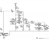
I'm not sure what you mean by "FB loop ground is lifted"? The actual feedback loop is from pin 1 to pin 2 of the op-amp via R7, C7, C10, C11 and VR2. If you disconnected pin 2 from R7 you have opened the loop at DC and the op-amp will slam into one of the power supply rails. Resistor R1 provides the input bias current.
If you're talking about lifting R15 from ground, it is part of what appears to be an EQ/effects/limiter circuit. But it's not a DC ground so it doesn't affect the DC operating point of the op-amp.
The op-amp is NOT a follower in this circuit. And the 4558 is a typical voltage op-amp and doesn't have any special characteristics.
There are lots of tutorials on the web that go over op-amp basics. And someone with more guitar amp experience than me can probably tell you more about exactly what the circuit is supposed to do. I try to design and build things that reduce distortion not increase it")
If you're talking about lifting R15 from ground, it is part of what appears to be an EQ/effects/limiter circuit. But it's not a DC ground so it doesn't affect the DC operating point of the op-amp.
The op-amp is NOT a follower in this circuit. And the 4558 is a typical voltage op-amp and doesn't have any special characteristics.
There are lots of tutorials on the web that go over op-amp basics. And someone with more guitar amp experience than me can probably tell you more about exactly what the circuit is supposed to do. I try to design and build things that reduce distortion not increase it
OK, thanks for your replies. I guess I should have been more detailed. I have this amp, so I know how this circuit behaves in reality.
When the switch shown in the bottom left corner is in the position shown (which lifts R15 from ground), this circuit element does "nothing" (i.e. the opamp does not add gain and the CR3-6 diodes do not clip the output), but is is the only signal path so the signal does absolutely go through it. When the switch is in the opposite position, grounding R15 and the diodes, the opamp stage adds gain and the diodes clip.
When the switch shown in the bottom left corner is in the position shown (which lifts R15 from ground), this circuit element does "nothing" (i.e. the opamp does not add gain and the CR3-6 diodes do not clip the output), but is is the only signal path so the signal does absolutely go through it. When the switch is in the opposite position, grounding R15 and the diodes, the opamp stage adds gain and the diodes clip.
The opamp open loop has infinite gain (sort of, for practical purposes). That means that for practical purposes, for any output signal, the difference between + and - input is pretty much zero.
So, if the feedback network is not connected to ground, only Vout to -Vin, the output will do whatever it needs to do to make +Vin = -Vin. Since no current (ideally) runs through the feedback network, +Vin = -Vin can only be when Vout=-Vin (which is also +Vin of course). So, there's your follower.
Now connect the feedback network path to ground. There now is a voltage divider between Vout, -Vin and ground. Just as the above, the Vout will do whatever it needs to do to make +Vin = -Vin which is the voltage at the feedback divider. NOW there is current from Vout through feedback to -Vin to ground. So, it is clear that -Vin can only be +Vin when Vout is higher than -Vin! How much? The same ratio as the feedback divider ratio. So there's your gain.
jd
- Status
- This old topic is closed. If you want to reopen this topic, contact a moderator using the "Report Post" button.
- Home
- Amplifiers
- Solid State
- How do opamps behave open loop?