This could be possible, but I have never tested.tiefbassuebertr
I think that when using NMOS only, one can pull out all the tube topologies out of the box.
Basicly it would be easy find out by the circlotron topology (= CSPP resp. PPP) without transformer (i. e. OTL)
If you have an OTL circlotron tube power amp GM-20 (Graaf) and a finished MOSFET circlotron diy project at the same time, you can comparable both of them and tell about the results.
I have heard both of them, but unfortunately not at the same time
here a URL about MOSFET CSPP
http://www.hinocatv.ne.jp/~s_suzuki/Uni_CSPP/UHC-MOS/UHC-MOS.htm
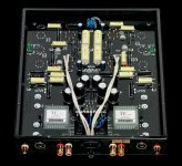
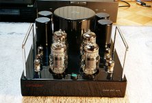
and two jpg's and a schematic about the GM-20:
Attachments
Last edited:
Phase splitter is best for the N-Channel Mosfet Drive topology.
Here are description a special quasi compl. version include a distortion removal circuit - of the japanese URL
Distortion removal circuit
and the automatic translation in English
Google Übersetzer
no comments to this topology from Japan?Here are description a special quasi compl. version include a distortion removal circuit - of the japanese URL
Distortion removal circuit
and the automatic translation in English
Google Übersetzer
It's cheap, it's N, it's dirty, it's.... The CIRCLOMOS!!!
another approach in this context
http://www.diyaudio.com/forums/solid-state/154388-its-cheap-its-n-its-dirty-its-circlomos.html
another approach in this context
http://www.diyaudio.com/forums/solid-state/154388-its-cheap-its-n-its-dirty-its-circlomos.html
can i suggest a serial dual differential ? it s balanced as
the phase spliting is naturally present in this topology...
i would go this way if i had only one kind of power devices...
Then you have an circlotron input stage - so I think (CSPP). Check out this thread:
http://www.diyaudio.com/forums/soli...e-ended-related-solid-state-output-stage.html
now there are additional topologies here on diyaudio, where used only N-Channel MOSFETs resp. only NPN BjTs: in the output power stage:
1) Circlomos from Elvee
http://www.diyaudio.com/forums/solid-state/154388-its-cheap-its-n-its-dirty-its-circlomos.html
2) Super-Pair Buffer from Linuxguru
http://www.diyaudio.com/forums/soli...-super-pair-buffer-simulation-schematics.html
3) Kenpeter's follower - three in one (very special) go to post #47 about
http://www.diyaudio.com/forums/soli...llower-diamond-buffer-power-output-stage.html
4) Class-B without crossover-distortion
http://www.diyaudio.com/forums/solid-state/160285-class-b-w-o-crossover-distortion-1975-a.html
Number 2, 3 and 4 I haven't investigate, but it looks very interesting. If the author have found a method for reliability stabilizing of the idle current through the output for number 1, we have a very fine power amp topology.
Last edited:
Member
Joined 2009
Paid Member
did you look at the schematic ? - the output is shorted to the -ve rail.
Member
Joined 2009
Paid Member

Member
Joined 2009
Paid Member
What you mean ?
I was joking about the output being connected to the power supply on the linked schematic - of course for Circlotron the power supply is floating so this is just fine !
I like this new design, I think hybrids is an interesting area to explore - I'm hoping to make something myself this winter - most likely based on diamond buffer - not a new approach but a good starting point.
N-ch output circuit designs
Linear OTL N-ch only output circuits can be made to work very well if not better than complementary output, without a lot of complexity once the underlying issues are clarified. There is no need for servo bias, the servo bias circuitry as presented in designs like Rohr's autobias (Siliconix App Note) and Auto Bias is a band aid for excessive dc operating drift issues in those discrete circuit designs. Ie the monolithic op amp(s) in these autobias approaches are basically a patch, a solution to a problem that derives from the circuit designer not doing an adequate job of meeting dc stability requirements in one or more of the discrete gain/driver stages. The basic circuit shown in Pat 5631608 (US Patent 5631608 - Driver for N-channel VFET output stage of power amplifier) with only 7 transistors (practical implementation) nicely removed all operating point drift in the driver (without autobias) and at the same time introduced the correct thermal compensation coefficient (~ -4.4 mV/C) at the gate to source of each output fet. The circuit was originally intended as an upgrade/design-around for a complementary output circuit (US Patent 4483016 - Page 1 Image - Audio amplifier) that was used under license in existing product. The new circuit not only sidestepped licensing royalties but also ended up reducing the BOM cost and performing better than its forerunner in terms of thermal stability, THD, and efficiency. Theres probably over 50,000 automotive amplifier units (Hafler MA-4, Rockford P45 & MTX TA 240 TA280 TA2300 TA4160 TA4320 and later models) out there in the field with a variant of that configuration. The bias tracked perfectly from -40 C to 100 C which is basically the peak ambient temp possible within the product enclosure (Alaska to Arizona trunk temp) etc. This circuit in conjunction with 2 TO-220's N-ch (IRF-540 etc) fets achieved 100 W @ 4 ohms with .035 % THD @ 20 khz - with no more than 50 mA of bias, the mid band distortion @ 1khz was .005 THD.
Linear OTL N-ch only output circuits can be made to work very well if not better than complementary output, without a lot of complexity once the underlying issues are clarified. There is no need for servo bias, the servo bias circuitry as presented in designs like Rohr's autobias (Siliconix App Note) and Auto Bias is a band aid for excessive dc operating drift issues in those discrete circuit designs. Ie the monolithic op amp(s) in these autobias approaches are basically a patch, a solution to a problem that derives from the circuit designer not doing an adequate job of meeting dc stability requirements in one or more of the discrete gain/driver stages. The basic circuit shown in Pat 5631608 (US Patent 5631608 - Driver for N-channel VFET output stage of power amplifier) with only 7 transistors (practical implementation) nicely removed all operating point drift in the driver (without autobias) and at the same time introduced the correct thermal compensation coefficient (~ -4.4 mV/C) at the gate to source of each output fet. The circuit was originally intended as an upgrade/design-around for a complementary output circuit (US Patent 4483016 - Page 1 Image - Audio amplifier) that was used under license in existing product. The new circuit not only sidestepped licensing royalties but also ended up reducing the BOM cost and performing better than its forerunner in terms of thermal stability, THD, and efficiency. Theres probably over 50,000 automotive amplifier units (Hafler MA-4, Rockford P45 & MTX TA 240 TA280 TA2300 TA4160 TA4320 and later models) out there in the field with a variant of that configuration. The bias tracked perfectly from -40 C to 100 C which is basically the peak ambient temp possible within the product enclosure (Alaska to Arizona trunk temp) etc. This circuit in conjunction with 2 TO-220's N-ch (IRF-540 etc) fets achieved 100 W @ 4 ohms with .035 % THD @ 20 khz - with no more than 50 mA of bias, the mid band distortion @ 1khz was .005 THD.
I was joking about the output being connected to the power supply on the linked schematic - of course for Circlotron the power supply is floating so this is just fine !
I like this new design, I think hybrids is an interesting area to explore - I'm hoping to make something myself this winter - most likely based on diamond buffer - not a new approach but a good starting point.
Another floating supply:
http://www.diyaudio.com/forums/solid-state/179475-its-only-need-50v-45v-outputs.html
Another one.
No schematic (its prevented to be published) , but I just post them long ago. All N-channel, tracking rails, and good crossing management.
http://www.diyaudio.com/forums/ever...si-not-bad-really-i-post-some-proof-here.html
Last edited:
can anyone .
can anyone try to sim this scheme of quasi mosfet.
Pictures by jon2xflash - Photobucket
can anyone try to sim this scheme of quasi mosfet.
Pictures by jon2xflash - Photobucket
<a href="http://s1096.photobucket.com/albums/g324/jon2xflash/?action=view¤t=mosfetv2.jpg" target="_blank"><img src="http://i1096.photobucket.com/albums/g324/jon2xflash/mosfetv2.jpg" border="0" alt="Photobucket"></a>
<a href="http://s1096.photobucket.com/albums/g324/jon2xflash/?action=view¤t=mosfetv1kit.jpg" target="_blank"><img src="http://i1096.photobucket.com/albums/g324/jon2xflash/mosfetv1kit.jpg" border="0" alt="Photobucket"></a>
<a href="http://s1096.photobucket.com/albums/g324/jon2xflash/?action=view¤t=mosfetv1kit.jpg" target="_blank"><img src="http://i1096.photobucket.com/albums/g324/jon2xflash/mosfetv1kit.jpg" border="0" alt="Photobucket"></a>
where are to find the schematics now from this old, follow website ??
http://web.archive.org/20030101000000*/http://www.aussieamplifiers.com/
I don't find the appropriate download aera about the currently version
High End Audio MOSFET Amplifiers
http://web.archive.org/20030101000000*/http://www.aussieamplifiers.com/
I don't find the appropriate download aera about the currently version
High End Audio MOSFET Amplifiers
The basic circuit shown in Pat 5631608 (US Patent 5631608 - Driver for N-channel VFET output stage of power amplifier) with only 7 transistors (practical implementation) nicely removed all operating point drift in the driver (without autobias) and at the same time introduced the correct thermal compensation coefficient (~ -4.4 mV/C) at the gate to source of each output fet.
I have looked at the patent, and I don't see how you can control the output bias without controlling the tail current (of the input differential pair).
check out the circuit by post #23 aboutI have looked at the patent, and I don't see how you can control the output bias without controlling the tail current (of the input differential pair).
http://www.diyaudio.com/forums/solid-state/162644-siliconix-siemens-nmos-amplifiers.html
check out also third URL about 1) by post #1 on this thread and follow:
http://www.diyaudio.com/forums/solid-state/143706-kaneta-methods-all-fet-power-amplifier.html
In all cases bias control is with help of thermal resistors.
If you want such a topology with bias servo, buy the book
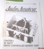
Audio Amateur "Power Amp Projects" - go to
audio amateur - power amp projects
or the magazine 2/1988 about
Audio Amateur Magazine Back Issue #2 1988 - Dayton
and read this articles:
A 40W All-MOSFET Power Amp (Part I) 2/1988
A 40W All-MOSFET Power Amp (Part II) 3/1988
(Chater's 40W Servo Controlled MOSFET Amp)
Check also this thread:
http://www.diyaudio.com/forums/solid-state/81436-william-t-chater-power-amp.html
and here the patent paper from this author:
http://www.freepatentsonline.com/5055797.pdf
Which commercial brands uses that topology?
Attachments
Last edited:
- Status
- This old topic is closed. If you want to reopen this topic, contact a moderator using the "Report Post" button.
- Home
- Amplifiers
- Solid State
- Only N-Channel MOSFETs (NMOS); better Audio from non complements by Audio Power?