To me your explanation makes it even more clear that the smoothing capacity needs to be much bigger for a bridged amplifier.megajocke said:For bass frequencies where it is needed most, a non-bridged amp uses only one half of the power supply energy storage at a time. By using the whole power supply all the time this waste of power supply energy storage capacity is mitigated.
Let me put some numbers to it. If you pass 1 A through an 8 Ohm load, a non-bridged amplifier needs to provide 8 V and 1 A. Each half of the power supply provides that current during one half cycle, so needs to supply an average of 0,5 A per half. In a bridged amplifier each half of the bridge provides 4 V and 1 A. So it takes 2 A for both bridges and the power supply has to provide that current continuously on both halves.
In a bridged amplifier you need four times the capacitance and four times the ripple current rating. To make things worse those capacitors don't have the time to cool down during every second half-cycle, so they will need much more air-flow around them or may even need to be heatsinked.
The Crown MA-600's configuration does not change anything about those figures. The Crown's big advantage is that it complies with safety regulations by connecting one side of the load to ground, thus providing a Class I protection for the speaker output. It is often overlooked, but such a measure is necessary as soon as the AC output can be bigger than 50 V or the DC output bigger then 120 V.
The numbers are right but the conclusion is wrong. 4 times the capacitance is correct, but you forgot that you halved the voltage! That's the same energy storage, not more. You are right that there isn't anything special to the Crown circuit in this regard. It's just that you can do away with the center tap and dual polarity supply and use less semiconductors than standard bridged amps.
So it might seem at first that there is no advantage, but the average current simplification doesn't work at low output frequencies around and below the mains frequency. In this range the ripple is determined by instantaneous current, not average. In your example the half-bridge amp needs two 8V 1A supplies while the bridged amp only needs two 4V 1A (equal to just one 8V 1A) supplies.
For a half-bridge amplifier the ripple voltage will go up about three times when you go down in frequency (peak-to-average ratio of power supply current is pi), keeping output level constant, assuming the transformer is large. For a bridge amp it will only go up 1.5 times, half of that. (peak-to-average ratio is pi/2)
4 x 0,5 = 2, not 1. You need four times the capacitance and double the energy storage.megajocke said:4 times the capacitance is correct, but you forgot that you halved the voltage! That's the same energy storage, not more.
The schematic shows a split supply and a standard bridged amp. The connection from one speaker terminal to ground and PE does not change anything about the way it works.megajocke said:It's just that you can do away with the center tap and dual polarity supply and use less semiconductors than standard bridged amps.
The current that flows in through the high-side flows out of the low-side. That means both sides consume 1 A, which is a total of 2 A for the power supply at 100 % duty factor from both halves of the power supply. The non-bridged amplifier consumes 1 A with 50 % duty factor for each half of the power supply. 2 A x 100 % = 2 A, while 1 A x 50 % = 0,5 A for each half of the power supply. A factor of 4:1 against the bridged amplifier.megajocke said:the half-bridge amp needs two 8V 1A supplies while the bridged amp only needs two 4V 1A (equal to just one 8V 1A) supplies.
Maybe you can expand on this a bit, because I am probably not the only one to whom this is news.megajocke said:For a half-bridge amplifier the ripple voltage will go up about three times when you go down in frequency (peak-to-average ratio of power supply current is pi), keeping output level constant, assuming the transformer is large. For a bridge amp it will only go up 1.5 times, half of that. (peak-to-average ratio is pi/2)
Until then I stick to what I learned and that is Vpp=I/(2*f*C). If the current draw is four times as big, you need a capacitor that is four times as big to maintain the ripple voltage the same. Anyhow, the ripple current will be higher for a bridged amp and the capacitors need an accordingly higher ripple current rating.
pacificblue said:
4 x 0,5 = 2, not 1. You need four times the capacitance and double the energy storage.
Energy storage is proportional to the square of the voltage. 4 * 0.5^2 = 1.
pacificblue said:The schematic shows a split supply and a standard bridged amp. The connection from one speaker terminal to ground and PE does not change anything about the way it works.
The split supply is for the op-amp bits. T100, D117 and C126 make up the power supply for one channel. I never said there is anything fundamentally different from a standard bridged amp, just that it doesn't need a full-blown amplifier circuit for the low side and that the PSU doesn't need a center tap.
Yes, the capacitance for equal HF properties is 4 times as large per side of the bridged amplifier's power supply, ie. it has the same amount of energy storage.Originally posted by pacificblue
The current that flows in through the high-side flows out of the low-side. That means both sides consume 1 A, which is a total of 2 A for the power supply at 100 % duty factor from both halves of the power supply. The non-bridged amplifier consumes 1 A with 50 % duty factor for each half of the power supply. 2 A x 100 % = 2 A, while 1 A x 50 % = 0,5 A for each half of the power supply. A factor of 4:1 against the bridged amplifier.
Originally posted by pacificblue
Maybe you can expand on this a bit, because I am probably not the only one to whom this is news.
Until then I stick to what I learned and that is Vpp=I/(2*f*C). If the current draw is four times as big, you need a capacitor that is four times as big to maintain the ripple voltage the same. Anyhow, the ripple current will be higher for a bridged amp and the capacitors need an accordingly higher ripple current rating.
Well, I guess this is the interesting part. The ripple formula you showed is correct of course, but what does the I in it mean? Instantaneous or average current? If the load current waveform is of high frequency it might just as well have been DC of its average value so there you can use the average current.
Let's take an extreme example of low frequency: A rectangle wave current is pulled from a PSU. It looks like this: 100A for 1 second, 0A for 99 seconds, repeat. You can't just put in the average current of 1A in this case of course. That should be obvious. The same is true for the amplifier PS at low frequency, although not as obvious - it's not average current that matters any longer.
The higher peak-to-average ratio in the half-bridge amplifier is what makes power supply ripple degrade more towards low frequencies than it does in the bridged one.
It's true that the ripple current in the capacitor(s) is higher, but it's not 4 times as high like you say, it's only sqrt(2) times higher. As an example, take an amplifier which delivers 1A RMS to the load:
Half bridge: each power supply delivers 1 / sqrt(2) A RMS.
Full bridge: each power supply side delivers 1A RMS, which is sqrt(2) times higher.
Capacitor ripple current is (although a bit simplified) proportional to power supply RMS current. If you keep the two capacitors from your half-bridge amp and put them into an equivalent size bridge amp which doesn't use the center tap, like the Crown topology for example, between plus and minus rail in parallell you have:
* the same energy storage as the original
* better bass performance, only half the ripple at LF
* lower ripple current by a factor of 1/sqrt(2) in the capacitors
You could remove one of the capacitors and get back the LF ripple properties of the old one, with half the energy storage. Ripple current would be sqrt(2) times higher than the non-bridged one though.
0,5^2 = 0,25, not 2, but the assumption is wrong anyway, so it does not matter.megajocke said:Energy storage is proportional to the square of the voltage. 4 * 0.5^2 = 1.
I have to admit that I had not looked at the power supply section before, but by skipping the center-tap the great advantage of using half the voltage rating is gone. There is no factor of 0,5. The capacitor has to be rated for the same voltage as in a non-bridged split power supply.
The amplifier circuit for the low side looks very much the same as the one for the high side to me. On the contrary it seems that the high side is more complex than normal, because it needs, what they call a 'Voltage Translator Stage', which is more or less a virtual ground.megajocke said:it doesn't need a full-blown amplifier circuit for the low side and that the PSU doesn't need a center tap.
How much does a center-tap cost?
The average current is a function of peak current and wave form. Nothing changes in the relationship.megajocke said:Well, I guess this is the interesting part. The ripple formula you showed is correct of course, but what does the I in it mean? Instantaneous or average current? If the load current waveform is of high frequency it might just as well have been DC of its average value so there you can use the average current.
You stated that in a previous post. Please explain, why that should be so.megajocke said:The same is true for the amplifier PS at low frequency, although not as obvious - it's not average current that matters any longer.
And please explain also, why a non-bridged amplifier has a lower ripple degradation than a bridged one. Ripple depends on the current draw. If the ripple remains more constant across different load situations, that implies the current draw rises proportionally less in a bridged amplifier than in a non-bridged. Do you assume that the bridged amplifier has a higher quiescent current?megajocke said:The higher peak-to-average ratio in the half-bridge amplifier is what makes power supply ripple degrade more towards low frequencies than it does in the bridged one.
megajocke said:It's true that the ripple current in the capacitor(s) is higher, but it's not 4 times as high like you say, it's only sqrt(2) times higher.
Which is it now? Proportional to the current draw or sqrt(2) times higher for 4 times the current? My vote remains for proportional.megajocke said:Capacitor ripple current is (although a bit simplified) proportional to power supply RMS current.
A bridged amplifier draws 2 A from the power supply to deliver 1 A to the load.megajocke said:As an example, take an amplifier which delivers 1A RMS to the load:
Half bridge: each power supply delivers 1 / sqrt(2) A RMS.
Full bridge: each power supply side delivers 1A RMS, which is sqrt(2) times higher.
On the original topic, I agree with RocketScientist, Steve Dunlap et. al. The transformer may be the single most expensive part so using one you have will save you money if it is suitable. It is suitable in this case, for a bridged amp. The 400W should be possible to meet unless the amplifiers used have unusually high rail loss.
I second the idea of using standard amplifiers and bridging them; the Crown circuit is just something I brought up when someone said you MUST build two complete amplifiers, which is, demonstrably, not true.
Absolute current, voltage and capacitance values don't say anything in themselves. The other two needs to be known too to be able to draw conclusions.
I second the idea of using standard amplifiers and bridging them; the Crown circuit is just something I brought up when someone said you MUST build two complete amplifiers, which is, demonstrably, not true.
Of course it's 0.25. And how much is 0.25 times 4, which was the question? One.pacificblue said:
0,5^2 = 0,25, not 2, but the assumption is wrong anyway, so it does not matter.
Having a center tap or not does not matter. Don't you know what happens to the capacitance of seriesed capacitors? It's the same energy storage either way. For example, a half bridge amp has one 100V 10mF capacitor per rail. The corresponding bridge amp would have one 40mF 50V per rail. That's equivalent to one 20mF 100V capacitor across the rails, ie. the two original caps in parallell.pacificblue said:
[...]but by skipping the center-tap the great advantage of using half the voltage rating is gone. There is no factor of 0,5. The capacitor has to be rated for the same voltage as in a non-bridged split power supply.
200€+ over here if I already have a suitable 80V 2000VA transformer, without centertap, which I wouldn't be able to use otherwise.pacificblue said:
How much does a center-tap cost?
The current waveform is different in the both cases, that's the whole point. It's the different peak-to-average ratio of the different waveforms that makes the difference in power supply utilization at low load current frequency. The peak-to-average ratio of PSU current is double in a half-bridge amplifier compared to a full-bridge.pacificblue said:
The average current is a function of peak current and wave form. Nothing changes in the relationship.
If it isn't obvious why you can't use average current in ripple calculations, when the frequency of the load current is low, I can't help you. Please look at the stupidly exaggerated example again.pacificblue said:
You stated that in a previous post. Please explain, why that should be so.
Please show some respect for the difference between peak values, instantaneous values, average values and RMS values. They are totally different quantities. Moreover, you can't just add and subtract RMS and peak values if waveforms are different. Also, please don't try to repeal the first law of thermodynamics. That the current draw (measured in some arbitrary way) is double in the bridge amp is irrelevant as the voltage (measured in a corresponding way) is halved. It's the difference in peak-to-average ratio of the current that gives you the advantage in a bridged amp.pacificblue said:
Which is it now? Proportional to the current draw or sqrt(2) times higher for 4 times the current? My vote remains for proportional.
[...]
A bridged amplifier draws 2 A from the power supply to deliver 1 A to the load.
Absolute current, voltage and capacitance values don't say anything in themselves. The other two needs to be known too to be able to draw conclusions.
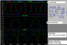
pacificblue, here are some waveforms.
The transformer for both cases is 35-0-35 (50V peak), practically ideal. Putting in parasitics gives an even greater advantage to the bridged amplifier.
Capacitors are 2x15mF, one per 50V rail in the half bridge amplifier. The full bridge amplifier has only one 15mF capacitor on its single 50V rail. The rectifier is a center-tap two-diode full wave in the bridge amplifier, not that it matters.
The load is 5A peak at 25Hz output from the amplifier. (for example 8 ohms driven to 40V peak) Mains frequency is 50Hz.
Here it can be clearly seen that peak-to-peak ripple voltage is the same for both amplifiers even though the half bridge needs double the amount of energy storage. If parasitics, mainly those of the transformer, are modeled too the advantage of the bridge amplifier grows even greater.
The ripple on the negative rail looks the same as on the positive , just out of phase, so its plot was omitted for clarity.
RMS ripple current in the capacitor of the full bridge is about 150% of the ripple current in a single capacitor of the half bridge. (Or 75% of the total ripple current if you want to look at it that way)
Attachments
megajocke said:200€+ over here if I already have a suitable 80V 2000VA transformer, without centertap, which I wouldn't be able to use otherwise.

You keep repeating that. Is there any chance that you support it with an explanation, a link, a reference, anything?megajocke said:The peak-to-average ratio of PSU current is double in a half-bridge amplifier compared to a full-bridge.
Which means, there is obviously no chance that you support that with an explanation, a link, a reference, anything.megajocke said:If it isn't obvious why you can't use average current in ripple calculations, when the frequency of the load current is low, I can't help you.
In this document from the Panasonic website it says on page 1 "Ripple current is the rms value of alternating current flowing through a capacitor".
As far as I understand that law, if you want 8 V and 1 A at a speaker, you can get that through an 8 V and 1 A power supply from a non-bridged amplifier or through a 4 V and 2 A power supply from a bridged amplifier. It does not matter, if you use peak, average, instantaneous or what-not-ever values. 4 x 1 just is not 8.megajocke said:Also, please don't try to repeal the first law of thermodynamics.
that the current consumption is doubled for the bridged amplifier, because it shows two sequential half-waves, while the non-bridged shows one followed by an equally long time along the 0-axis.megajocke said:Here it can be clearly seen..
Looks like the same peak value and half the rms value on the non-bridged amplifier to me. Do you agree that the ripple factor is Vripple(rms)/Vdc as defined e. g. on Wikipedia? Then the capacitor needs to be double the size for the single supply bridged amplifier to achieve the same ripple factor. And to answer your question, I do know, what happens with series-connected capacitors, which makes me suspect that you come out at four times the capacitance with a split supply bridged amplifier.megajocke said:The ripple on the negative rail looks the same as on the positive , just out of phase, so its plot was omitted for clarity.
And with double the capacitance for the single supply bridged amplifier? And with four times the capacitance for a split supply bridged amplifier?megajocke said:RMS ripple current in the capacitor of the full bridge is about 150% of the ripple current in a single capacitor of the half bridge.
I suggest, we stop this discussion here, so that others can remain on topic. If you want to keep the topic alive, we should have the thread split or open another one.
I have used the "report" button and requested that our posts be split off to their own thread
Power consumption is the same. The half bridge amplifier had two such 50V supplies providing 5/pi = 1.6A average each. The full bridge has one 50V supply providing double the current of one such supply, 5 * 2 / pi = 3.2A. You could look at it like two 25V supplies in series providing 6.4A total, but that's just confusing and contraproductive.
In both cases the peak of the PSU current (see that diagram again) is 5A. The bridge amplifier draws 3.2A average while the half-bridge needs 1.6A average from each side of the supply. There's your higher peak-to-average ratio in the half bridge.
More importantly, it's the same ripple valley voltage, and this is what the amplifier cares about as the amplifier clips instantly if supply voltage drops under what it's needing. The amplifier doesn't care about Wikipedia's definition of "ripple factor".
that the current consumption is doubled for the bridged amplifier, because it shows two sequential half-waves, while the non-bridged shows one followed by an equally long time along the 0-axis.
Power consumption is the same. The half bridge amplifier had two such 50V supplies providing 5/pi = 1.6A average each. The full bridge has one 50V supply providing double the current of one such supply, 5 * 2 / pi = 3.2A. You could look at it like two 25V supplies in series providing 6.4A total, but that's just confusing and contraproductive.
"The peak-to-average ratio of PSU current is double in a half-bridge amplifier compared to a full-bridge." You keep repeating that. Is there any chance that you support it with an explanation, a link, a reference, anything?
In both cases the peak of the PSU current (see that diagram again) is 5A. The bridge amplifier draws 3.2A average while the half-bridge needs 1.6A average from each side of the supply. There's your higher peak-to-average ratio in the half bridge.
Looks like the same peak value and half the rms value on the non-bridged amplifier to me. Do you agree that the ripple factor is Vripple(rms)/Vdc as defined e. g. on Wikipedia? Then the capacitor needs to be double the size for the single supply bridged amplifier to achieve the same ripple factor. And to answer your question, I do know, what happens with series-connected capacitors, which makes me suspect that you come out at four times the capacitance with a split supply bridged amplifier.
More importantly, it's the same ripple valley voltage, and this is what the amplifier cares about as the amplifier clips instantly if supply voltage drops under what it's needing. The amplifier doesn't care about Wikipedia's definition of "ripple factor".
There you have it. And double the current needs double the capacitance for the same performance. That is, what AndrewT and Jan Dupont pointed out in the original thread and what I agree to.megajocke said:Power consumption is the same...
Yes. And where is the connection to the frequency that you claimed in post #2?megajocke said:In both cases the peak of the PSU current (see that diagram again) is 5A. The bridge amplifier draws 3.2A average while the half-bridge needs 1.6A average from each side of the supply. There's your higher peak-to-average ratio in the half bridge.
megajocke said:For a half-bridge amplifier the ripple voltage will go up about three times when you go down in frequency (peak-to-average ratio of power supply current is pi), keeping output level constant, assuming the transformer is large. For a bridge amp it will only go up 1.5 times, half of that.
And that depends on when it clips.megajocke said:it's the same ripple valley voltage, and this is what the amplifier cares about as the amplifier clips instantly if supply voltage drops under what it's needing.
The bridge amplifier passes through that valley twice as often as the non-bridged. That means both amplifiers will show the same clipping behavior during 50 % of the time. During the remaining 50 % the non-bridged amplifier will clip at a higher voltage than the bridged amplifier. Advantage for the non-bridged configuration?
If you increase the capacitance for the bridged amplifier, you can level that out. The ripple factor will reach the same level as for the non-bridged, but the valley will not dip down as much, so the bridged will keep on clipping earlier then the non-bridged during 50 % of the time, but will clip later during the remaining 50 %.
It is not Wikipedia's definition. Wikipedia is only one of many sources, where you can find the definition. You can derive the importance of the ripple factor from your own definition of, when an amplifier clips. Lower ripple factor -> lower supply rail dip -> higher clipping level.megajocke said:The amplifier doesn't care about Wikipedia's definition of "ripple factor".
pacificblue said:
And that depends on when it clips.
The bridge amplifier passes through that valley twice as often as the non-bridged. That means both amplifiers will show the same clipping behavior during 50 % of the time.
Sure, but if it "only" clips 50% of the time, it still clips and fails to deliver that power. Observe that this is with only one 50V 10mF cap instead of two so there is some advantage at least!
Another way of looking at it is that one PSU capacitor in the half-bridge amp sits idle 50% of the time, when there is no current draw, and during that time it might as well not be there. So you end up with only one capacitor at a time doing anything, and being needed. Could we share one capacitor in some way this waste would be no more. But, wait! That's the bridged amp
If it is the behaviour when driven into heavy overload you are worried about, it is pretty similar for these two configurations. The turnover frequency of load resistance and power supply capacitance is the same in both cases. If you keep the energy storage of the non-bridge in the bridged amp the bridged amp will have an advantage.
But you are right too. If the power supply is built with center tap and split rails the advantage in power supply size disappears as the lower energy storage requirement is offset by lower voltage capacitors having lower energy storage density. But the low voltage capacitors may be cheaper and/or more available, still making bridge a good idea from this viewpoint.
In the end, the main advantage of bridge configuration is really that the voltage stress on output devices/ICs is halved, which is a big deal at higher output powers (look at the SOA of 2SC5200 for example). MJ1502x/MJ2119x devices, cascoding or class G/H is another option at high power, if you want to go that route.
A bridge circuit also lets you use a non-center tapped transformer in a DC-coupled amplifier if you want. I would probably not choose to build a bridge amplifier just because of its slightly better utilization of PSU caps, but the "I already have the transformer" reason and/or lower voltage stress on transistors are big ones.
If I'm just after the PSU utilization then there is a trick, which I've seen used in some stereo amps, to get better PSU utilization, without needing to go full bridge, which takes advantage of low frequency stuff usually being in phase in the two channels: Run one channel inverted and swap the output terminals.
Sounds like putting weight into the boot of a car, so that all those HP don't sit idle, while you drive below Vmax.megajocke said:Another way of looking at it is that one PSU capacitor in the half-bridge amp sits idle 50% of the time, when there is no current draw, and during that time it might as well not be there.
A capacitor may need the "idle" time to cool down. Ripple current rating is just another word for possible heat dissipation. Double the current draw -> double the ripple current -> double the heat dissipation. The means you need either higher ripple current rating or more air-flow around the capacitors or even capacitor heatsinking. Any of the three makes an amplifier more expensive and bigger without any gain in performance.
Non-bridged does not rule out single supply.megajocke said:A bridge circuit also lets you use a non-center tapped transformer in a DC-coupled amplifier if you want. I would probably not choose to build a bridge amplifier just because of its slightly better utilization of PSU caps, but the "I already have the transformer" reason and/or lower voltage stress on transistors are big ones.
That trick is used in Class D amplifiers to suppress power supply pumping. The PSU utilization remains the same, only the wave-form changes more towards an average value.megajocke said:If I'm just after the PSU utilization then there is a trick, which I've seen used in some stereo amps, to get better PSU utilization, without needing to go full bridge, which takes advantage of low frequency stuff usually being in phase in the two channels: Run one channel inverted and swap the output terminals.
But it's quite simple actually - current is drawn from each power supply only 50% of the time in a non-bridged amplifier. At low output frequencies this makes the power supply caps sit idle 50% of the time. A bridge amplifier (or a stereo amp with one channel inverted and typical program material) uses all capacitors all the time, giving somewhat better PSU utilization.pacificblue:
And that depends on when it clips. The bridge amplifier passes through that valley twice as often as the non-bridged. That means both amplifiers will show the same clipping behavior during 50 % of the time.
That's not correct, though I was too tired yesterday to see it.
During that time you speak of, when the voltage is up and high on the positive rail, current is drawn from the negative rail - which shows an identical valley during this time - giving the same ripple valley voltage as the bridge amplifier during that time.Also you say that ripple current is higher. Total capacitor ripple current is lower. In the bridged amplifier it's about 70% of the total capacitor ripple current in the half bridge, as I have already pointed out. If the same set of capacitors are used in both amplifiers, without reduction, the ESR heating in the bridged one is about half.
But yes, in the case of halving the PSU capacitance by removing half of the capacitors, the ripple current in a single capacitor is ~140% of the original. Yes, the capacitor needs higher ripple current rating - but it needs only half the capacitance! If the same type of capacitor can be used, the total ESR power loss will be the same in both configurations. This may or may not be acceptable, depending on how close it was to begin with.
I do not see much point in discussing such a subtle difference any more as it has become clear that your arguments are mostly based on erroneous assumptions such as capacitor energy storage and heating being proportional to the voltages and currents involved. Also, you bring up definitions of irrelevant terms such as "ripple factor", which have nothing to do with the problem at hand.
Further, you bring up things like "higher dissipation due to higher ripple current" and, at the same time, you say it gets even worse because of "no time to cool down". What you conveniently disregard is that these two things are exactly the same effect, explained in different ways. It's exactly the same thing and it's all covered by "higher ripple current".
Additionally, you have repeatedly disregarded the differences between average, RMS and instantaneous values - mixing them as you see fit trying to make your case - and I've seen this in other threads too. Finally, it must of course be remembered that bridge amplifiers have disadvantages of their own, but better PSU utilization is one of their advantages.
You are mixing up the current draw of the amplifier from the PSU at audio frequencies with the current draw of the capacitors from the transformer. The times, when they coincide in the way you describe, are too rare to be of much significance. Or are you only listening to 50 Hz sine waves that are in phase with mains?megajocke said:During that time you speak of, when the voltage is up and high on the positive rail, current is drawn from the negative rail
Wrong again. P=I²xR. If the current is 1,4 times higher and ESR remains the same, the power to dissipate is twice as much, just when you use a smaller capacitor that can dissipate less heat due to its size. By the way, smaller capacitors of the same type have higher ESR due to their size, so the situation gets even worse.megajocke said:But yes, in the case of halving the PSU capacitance by removing half of the capacitors, the ripple current in a single capacitor is ~140% of the original. Yes, the capacitor needs higher ripple current rating - but it needs only half the capacitance! If the same type of capacitor can be used, the total ESR power loss will be the same in both configurations.
There is no such thing as better PSU utilization. What goes in, goes out. If you think, it is good to use capacitors or other components at their limits, you can do that in a non-bridged amplifier just the same.megajocke said:better PSU utilization is one of their advantages.
pacificblue said:
You are mixing up the current draw of the amplifier from the PSU at audio frequencies with the current draw of the capacitors from the transformer. The times, when they coincide in the way you describe, are too rare to be of much significance. Or are you only listening to 50 Hz sine waves that are in phase with mains?
The don't have to be in phase for it to be better. Try simulating or measuring it.
pacificblue said:
Wrong again. P=I²xR. If the current is 1,4 times higher and ESR remains the same, the power to dissipate is twice as much, just when you use a smaller capacitor that can dissipate less heat due to its size. By the way, smaller capacitors of the same type have higher ESR due to their size, so the situation gets even worse.
I wrote TOTAL. It's ONE capacitor instead of TWO. ONE capacitor with DOUBLE the dissipation will give the SAME total dissipation as earlier. This is only a problem if ripple current rating were on the edge to begin with. Do YOU think "it is good to use capacitors or other components at their limits"?
Or use 1.4 times the capacitors in the bridge amp, keeping ripple current in each the same as earlier. It is still a smaller power supply.
pacificblue said:There is no such thing as better PSU utilization. What goes in, goes out. If you think, it is good to use capacitors or other components at their limits, you can do that in a non-bridged amplifier just the same.
Have you ever heard of power factor?
A half bridge amp delivering a 5A peak sine from a +-50V DC supply:
Delivers 5A * 0.707 = 3.5A RMS to the load
Draws 3.5A * 0.707 (half wave) = 2.5A RMS from each supply
Draws 5A / pi = 1.6A average from each power supply
50V RMS * 2.5A RMS = 125VA per side, 250VA total
50V * 1.6A = 80W per side, 160W total
A full bridge amp delivering a 5A peak sine from a 50V DC supply:
Delivers 5A * 0.707 = 3.5A RMS to the load
Draws 3.5A * 1 = 3.5A RMS from the supply
Draws 5A / pi * 2 = 3.2A average from the power supply
50V RMS * 3.5A RMS = 175VA total
50V * 3.2A = 160W total
Power drawn is the same, but RMS current and apparent power delivered to the amplifier from the power supply is 40% higher in the half bridge. This needs a somewhat bigger power supply to keep losses and ripple down.
No, you wrotemegajocke said:I wrote TOTAL.
megajocke said:the ripple current in a single capacitor is ~140% of the original.
I know, what it is. Now I wonder, what would make the non-bridged amplifier more inductive (or more capacitive?) than the bridged one.megajocke said:Have you ever heard of power factor?
Half-wave means 0,5 times 3,5 A, not 0,707 times, hence the consumption is the same for both amps.
I will now unsubscribe from this thread. It is obvious to me that you are not after facts, but only after winning the argument to satisfy your pride.
I'm not sure if this has been covered, but if it's any help, one reason some pro amps go to the extra expense of a grounded bridge design is to make better utlization of the power supply. If grounded bridge didn't let them use a cheaper power supply, I'm fairly sure they wouldn't use it.
RocketScientist said:I'm not sure if this has been covered, but if it's any help, one reason some pro amps go to the extra expense of a grounded bridge design is to make better utlization of the power supply. If grounded bridge didn't let them use a cheaper power supply, I'm fairly sure they wouldn't use it.
That's exactly the point here
Another reason is that the halved voltage stress on the output devices gives them better SOA. It also integrates nicely with the analog SOA computer circuit in the Crown, letting it sense device current easily while still being referenced to ground.pacificblue:
What I wrote in that paragraph was:
If the same type of capacitor can be used, the total ESR power loss will be the same in both configurations.
See there. Total ESR power loss. Half the number of capacitors with double the loss each gives the same total loss. The sentence you quoted, however, said nothing about power loss at all.
I know, what it is. Now I wonder, what would make the non-bridged amplifier more inductive (or more capacitive?) than the bridged one.
It's harmonic currents, nothing to do with the phase of the current. Only the DC component of the PSU current delivers power to the amplifier. It's just like in power distribution where only the 50Hz (or 60Hz) component of the current delivers power to the load. Other components of the current only cause wire heating.
Half-wave means 0,5 times 3,5 A, not 0,707 times, hence the consumption is the same for both amps.
That is a very common misconception and is NOT the case when talking about RMS current. It is related to P=I²xR. Removing every other half cycle will halve dissipation in a resistor. Thus RMS current is 0.707 times as big, otherwise dissipation wouldn't halve.
If you don't believe that, solve the integral or look it up.
megajocke said:
That's exactly the point here
And at the lower VCE, the SOA is purely thermally limited (no derating for voltage). That makes the "calculations" easier - it's just a multiplier circuit and a couple of time constants.
- Status
- This old topic is closed. If you want to reopen this topic, contact a moderator using the "Report Post" button.
- Home
- Amplifiers
- Solid State
- PSU capacitor design