Hello,
I have created a power supply for a LeCroy 9354 Digital Oscilloscope using pc supplies as they are powerful and cheap.
The scope boots up and works seemingly well until I turn the timebase to 50uS or less then a relay switches inside for the new time range followed shortly by the reboot of the scope.
I have heard that giving the scope noisy supply rails will limit the available bandwidth of a scope such as this (500MHz, 2Gs/s).
Id like to obtain close to the original spec from this puppy if possible.
Before going too far down the line of repair id like to know if this is the cause and what the most appropriate solution is?
Edit: One more thing can somebody please provide me with a link or PDF of Jungs' articles on "Regulators for High-Performance Audio" they appear to have been removed from the web?
Many thanks.
They seem to still be up at Walt's site: http://waltjung.org/Library.html
Click Regulators & References and look halfway down.
Can't help you with your poor hacked scope though
Click Regulators & References and look halfway down.
Can't help you with your poor hacked scope though
Craig405 said:
I have heard that giving the scope noisy supply rails will limit the available bandwidth of a scope such as this (500MHz, 2Gs/s).
Id like to obtain close to the original spec from this puppy if possible.
Before going too far down the line of repair id like to know if this is the cause and what the most appropriate solution is?
Hmmm... The ADC's in the scope should have little to do with the microcontroller that runs the user interface, etc. So noise in the converters, and re-booting are clearly two different issues (as you may realize). It's true high performance ADCs need a good power supply. But the power conditioning is usually close to the ADCs themselves not on a different board or module. So, with some luck, the quality of the actual power supply is less of an issue.
Given your scope has had a hard life from your other thread, I'd suspect some hardware damage (sadly) from the previous power supply problems. Or perhaps an entirely different problem. And when you switch time ranges some sort of invalid (i.e. unforeseen by the firmware developers) set of conditions occurs that causes the firmware to crash. Most instruments have a watchdog timer that will reboot them if the firmware crashes.
It's possible the actual noise from the relay coil is causing the problem, but that doesn't seem likely. I would think Lecroy would have properly suppressed the relay inductance, etc. It's much more likely something serious is wrong somewhere.
Does it pass its self test(s) and calibration? Sadly, scopes these days are so highly integrated with lots of custom FPGAs, ASICs, and other programmed devices, in BGA (ball grid array) packages, component level repair of much of the scope is not feasible by anyone other than the factory and they might not even attempt it given the high cost to remove and replace even a single BGA. So repair is generally limited to replacing, typically very expensive, entire circuit boards. But you probably already know that

Craig405 said:Hi RocketScientist, Thanks for the response. Do you think its likely to be a damaged piece of hardware then? Would it be worth me giving it a run from some bench supplies in the future to be sure?
I guess that depends on how easy that is to do? It couldn't hurt. Does it fail its self test and self calibration? Have you tried contacting Lecroy? Sometimes you can get a sympathetic person who might be willing to offer advice. The good news is you can get some almost decent digital scopes these days for vastly less than your LeCroy cost. In fact, several are probably cheaper than having your LeCroy repaired.
Hi, I forgot to answer you on those points, it doesnt seem to do a self test / self calibration (that it will display for me anyway). I think these are supposed to be run from a floppy drive but i dont have the diagnostic software.
I might ask lecroy for it as its surely free.
I was playing around with the scope tonight and discovered a few strange behaviours:
1) Reducing the number of points stored from waveform acquisition enables me to move the time base down to 10ns (previously couldnt get past 50uS) or so before i get a crash.
2) Using the scope to measure its own rails I get nasty noisy periods of 1-2V pk-pk every so often from the 15V SMPS's im using to power this thing. The last noisy period i observed ended with a scope crash, can i draw a conclusion about supplies here or does the fact I am using the scope to measure its own supply make the measurement pointless lol.
In fact casting my mind back to when i had a lab to test this thing in a year ago it ran perfectly well from some expensive 50A bench supplies (four of the things!) without crashing on me once and I was fiddling with the timebase at 2nS too. Ps this was after I had finished exploding it
Roar, thanks again for the kind offer if I had any money I might just have been interested in that (im an unemployed student haha!).
If you have access to lab supplies, it's worth a try. Using the scope to measure its own supplies might be suspect--it's hard to say.
Have you tried simply adding more capacitance to the supply rails as close to the scope's boards as possible? If there's ample capacitance, and you're certain the scope isn't triggering the current limiting or otherwise causing your supply(ies) to drop out of regulation, I would still suspect some other problem--especially if it's old enough to have a floppy drive
I would guess the scope has a switching regulator, or a few of them, to power the high speed digital circuitry which typically needs from 1.2 - 3.3 volts. The electrolytic capacitors in those regulators have a hard life and tend to get weaker with age. It's a common problem on old PC motherboards for the switching regulator that powers the CPU, etc. to start to get marginal causing instability as the caps age (or even sometimes outright fail).
It's possible replacing the regulator caps might solve your problem. Especially if you're feeding the regulators with less than clean power, it be exposing any bad or weak filter caps.
I'm sure LeCroy has a service manual for your scope, if you don't have it already, but most are just for board level repair. They usually don't give you schematics or details of the individual boards. Still, you should be able to identify the caps as they'll be near some power MOSFETs (probably surface mounted to the PCB) and one or more inductors.
The regulators are usually located as close as possible to the most power hungry chips they're feeding (i.e. the ones that run hottest) So they can be anywhere in the scope and there are likely more than one. Look at a PC motherboard around the CPU socket for an idea of what the circuits typically look like if you're not familiar with them.
Replacing those caps, assuming you can find and get to them, should be a relatively cheap repair. But it may or may not fix your problem.
I dont have access to lab supplies yet, i have to wait a few months to use a university lab. Would be so convenient right now though!
Its a 1996 scope i Believe, its old yes but its pretty fast and most of the bells and whistles of a modern high priced scope, and doesnt run XP like the newer Lecroys do
I may have trouble getting to the mainboard in this thing its all very tightly shielded and id have to do some serious disassembley.
I think ill try as you say and put some localised capacitors as close as possible.
how about 50uH inductor -> 1500uF // 10uF tantalum // 100nF film on each 5V rail, should that do a pretty good job?
For the analogue supplies 2200uF // 10uF tantalum // 100nF film.
Ideally if i can solve this problem by cleaning the supplies up then id use a linear supply on the 15V's and try to modify some good regulators like the jung super.
On the main PCB's i wouldn't try to add parts - simply renew the electrolytic capacitors already there.
what you may want to do is put some capacitance, say 1000uF in the scope where the power supply pcb wouldve been, to minimise the effects of the long cables from the PC PSU's.
Also, how are you getting +15/-15V from PC PSU's ? they typically only supply 12v.
what you may want to do is put some capacitance, say 1000uF in the scope where the power supply pcb wouldve been, to minimise the effects of the long cables from the PC PSU's.
Also, how are you getting +15/-15V from PC PSU's ? they typically only supply 12v.
Craig405 said:Its a 1996 scope i Believe, its old yes but its pretty fast and most of the bells and whistles of a modern high priced scope, and doesnt run XP like the newer Lecroys do
I may have trouble getting to the mainboard in this thing its all very tightly shielded and id have to do some serious disassembley.
One other thought is grounding. If you've somehow altered the grounding for the power rails that could be creating ground loops or have ground currents flowing where they're not welcome. Try to re-create the original grounding as closely as possible.
Also, always think "loop area" when handling any wiring that carries any sort of significant current around sensitive circuits (including digital circuits). In this case that means keeping the power and ground wiring twisted or bundled together and as short as possible. If the power and ground wiring, or even the two rails, are split apart, and forms any sort of "loop" (open space between the conductors) you just created an antenna that will broadcast all the current spikes on the power supply throughout the scope's circuitry. Those spikes could well glitch sensitive logic causing the re-boot you're seeing.
Given the age of your scope it probably has some really power hungry circuitry in it. It was harder to do 2 Ghz sampling in the mid 90's. So, somewhat revising my earlier opinion, I'd say you may well have a power problem. It could be your hacked supply isn't up to the job, it could be a ground or loop area issue, it could be you need more capacitance close to where the power is needed, or it could be the switching regulators are getting marginal.
If you can clean up the power without taking the scope apart, and that solves the problem, great. Otherwise, you have nothing to lose by taking it apart further and replacing the switching regulator caps (unless it's partly usable as is and you're worried about breaking something).
And, AFAIK, the more popular and lower-end new LeCroys don't run any flavor of Windows. I know Agilent and Tek both largely gave up on that approach for a whole bunch of reasons. I think LeCroy even finally has a sub $1000 scope now to compete with similar models from Agilent and Tek.
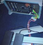
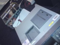
Jaycee, I meant to put these parts in the leads to the scope, ill attach some photos to be clearer . I would break out the molex in the first pic and insert a filtering board, or even shorten the wires from the scope and fix it inside in the old PSU bay.
My +/-15V is generated from two laptop power supplies (toshiba) but they are knock offs from Ebay and im suspicious of their power quality.
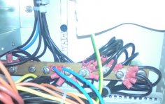
Grounding could be a an issue, I tried to give the power supplies and scope a good start with a star ground via a large copper bus bar (see next photo) whilst im sure this is much better than splicing wires all over the place there may still be issues with long wires to the scope and from the PC supplies themselves.
I also used every ground wire available from the PSU's 24 way molex to minimise resitances from bus bar back to the SMPS.
I hope there is minimal loop opportunity as I have tightly bundled wires to the scope but i didnt twist
The coloured cable going to the scope has:
10 molex connectors occupied with ground wires
10 wires for +/- 5V
4 wires for the +/-15V
Yep this thing is thirsty! LeCroy told me to provide:
-5.2V @13A
+5.2V @14A
-15.1V @ 4.5A
+15.1V @ 4A
MY two ATX power supplies are brand new antec units that can do 20A on the 5V rail each and the laptop PSU's can do 5A at 15V.
I think ill go ahead and start shortening wires as much as possible and if you think my above suggestion of the LC filtering for the 5V rail is suitable ill implement this as close to the scopes internal power connector as possible (but still inline with the wires)
phewf that was a biggun!
P.s. i have acquired a load of ferrite clip on beads, would placing these on the ends of the wires also be beneficial?
. I would break out the molex in the first pic and insert a filtering board, or even shorten the wires from the scope and fix it inside in the old PSU bay.My +/-15V is generated from two laptop power supplies (toshiba) but they are knock offs from Ebay and im suspicious of their power quality.
Grounding could be a an issue, I tried to give the power supplies and scope a good start with a star ground via a large copper bus bar (see next photo) whilst im sure this is much better than splicing wires all over the place there may still be issues with long wires to the scope and from the PC supplies themselves.
I also used every ground wire available from the PSU's 24 way molex to minimise resitances from bus bar back to the SMPS.
I hope there is minimal loop opportunity as I have tightly bundled wires to the scope but i didnt twist
The coloured cable going to the scope has:
10 molex connectors occupied with ground wires
10 wires for +/- 5V
4 wires for the +/-15V
Yep this thing is thirsty! LeCroy told me to provide:
-5.2V @13A
+5.2V @14A
-15.1V @ 4.5A
+15.1V @ 4A
MY two ATX power supplies are brand new antec units that can do 20A on the 5V rail each and the laptop PSU's can do 5A at 15V.
I think ill go ahead and start shortening wires as much as possible and if you think my above suggestion of the LC filtering for the 5V rail is suitable ill implement this as close to the scopes internal power connector as possible (but still inline with the wires)
phewf that was a biggun!
P.s. i have acquired a load of ferrite clip on beads, would placing these on the ends of the wires also be beneficial?
Attachments
Those are some long wires. You def. should have some serious capacitors as close to the scope as possible (see my earlier comments). And, ideally, the caps should ground to the respective grounds for each rail--again, as close as possible to where the power feeds the scope's boards.
Is the ground bar your addition? A star ground might not be the best approach if that's not what the old supply used. LeCroy may have intentionally isolated some of the ground paths for different supply rails. And if you tied them together, even on a bus bar, you might be creating problems. So I'd trace out how the old grounds terminated and try to duplicate that as closely as possible.
Generally, at some point, I would expect the scope to have completely isolated ground returns for the digital and analog grounds. Where that happens in the scope, I don't know. But if you tie those points together in some arbitrary place you're may degrade the analog performance and possibly create other problems.
Also, some PC power supplies dislike having most of their load on a single voltage. They're not designed for that and they may not function correctly. The feedback loops in the power supply have to balance the needs of the various output voltages against the PWM duty cycle. And some have minimum load requirements on the outputs or they're prone to tripping their overvoltage, falling out of regulation, or other problems.
In modern PC's it's often the 12 volt supply that's used (via the 4 pin ATX connector) to feed the hungry CPU switching regulator. In older PC's it's the 3.3 volt output. So if your PC supplies have no 12 volt or 3.3 volt load, they might fall out of regulation trying to provide 15+ amps at 5 volts because the lack of load on the other outputs is causing the PWM duty cycle to be way too low.
Also, check out http://circuitspecialists.com/level.itml/icOid/8518 for cheap single voltage 5 and 15 volt supplies that have an adjustment trim to give you 5.2 volts. They may also have a dual or triple that would work. You can get full data at Power One.
Ok heres what ill do:
1) shorten all wires as much as possible.
2) find the analogue ground wire(s) and keep them seperate of the 5V GND. I checked the LeCroy PSU and it does indeed appear to have seperate grounds, cheers I never thought to check this
3) build a board inside the scope in the old PSU bay with a load of inductors and caps, anything else worth adding to this board before i build it?
4) ill maintain the star bus for the 5V ground.
5) shall i connect the isolated 15V analogue ground to chasis earth via 10 ohms or so?
5V ground is connected to earth by default due to the internals of the SMPS.
With respect to the loading of rails on the PC PSU's, I actually did this with appropriate resistors and a heatsink but removed it as it worked fine without. Putting this back is no problem.
That link you gave is excellent! I may pick up
http://circuitspecialists.com/prod.itml/icOid/9105
to replace the PC supplies, the specs are better and theyre really cheap, just need to find a UK supplier.
By the way thanks for your continuing help, im learning quite a lot here!
Try to use a DMM or visual inspection to see what LeCroy did with the analog ground. Usually it gets tied somehow to either the main star ground, earth, etc. It might be directly (at the right point), through a resistor or resistor/cap combination.
I also don't think you need inductors. At the currents you're talking about they will be somewhat expensive and could even cause problems if they're not sized correctly. I'd use no more than 4700uf for the 5v supplies and 1000uf for the 15 volt supplies with a 0.1uf stacked ceramic or film cap across them. Anything more is probably overkill, and your supplies may not appreciate the start-up surge current of larger caps (it might trip the over current limit).
And before you make a fancy board, you can probably just temporarily solder things up hanging in space to see if it's going to work. You also probably want to experiement with grounding before making the board to find out what works, or doesn't work.
As for loading your PC supplies that's hard to know if you don't have a scope to monitor the rails. I guess I might temporily add the loads back (if you still have them) and if you get the scope working correctly, you could then try removing them and see if it makes any difference then. But for now, the more problem areas you can try to rule out, the better.
And I forgot you're in the UK. Those power supplies really are a bargain. And I've had good luck using them a few of them for various applications.
If this was me, I would probably look at getting some 18-24V supply that can supply some hefty power, and then build a DC-DC board to go where the old PSU went. Linear or Fairchild will probably have some suitable regulators to turn 18-24V into a symmetric 5V at hefty amperage (with external switching mosfets).
For the 15V supplies i'd use linear regulation with a gyrator to clean up the SMPS crap.
For the 15V supplies i'd use linear regulation with a gyrator to clean up the SMPS crap.
Just got back from a weekend away, got more time now to sort this power supply out now.
Ill imitate as far as i can tell what LeCroy have done for the grounds.
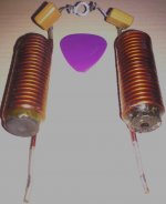
Im also a bit wary of using inductors, ill attach an image of the beasts i had in mind, an uneducated guess would say they are in the order of uH's maybe 50-100uH and i know for sure they are rated at around 30A .
.
So this eliminates cost and power issues but if they arent appropriate in an LC configuration suppling logic then ill leave them out, I assume there are conditions where they might cause oscillation with the C's?
Jaycee, I did have a look at some DC-DC converters from Traco actually but they were very expensive, however I didnt look at Linear or Fairchild. Also money being a factor and desk space ( i can stack my current solution under the scope neatly) the beasty Krell look-a-like bench supplies are off limits too
But Im all in for Linear 15V supplies and have been looking at Jung regulators with LM1084's (5A LDO variable) in the front end and seeing if the circuit can be modified with good performance to give the currents i need.
Ive read a little about 'Gyrators' as Wavebourne has used them recently.
Ill imitate as far as i can tell what LeCroy have done for the grounds.
Im also a bit wary of using inductors, ill attach an image of the beasts i had in mind, an uneducated guess would say they are in the order of uH's maybe 50-100uH and i know for sure they are rated at around 30A
.So this eliminates cost and power issues but if they arent appropriate in an LC configuration suppling logic then ill leave them out, I assume there are conditions where they might cause oscillation with the C's?
Jaycee, I did have a look at some DC-DC converters from Traco actually but they were very expensive, however I didnt look at Linear or Fairchild. Also money being a factor and desk space ( i can stack my current solution under the scope neatly) the beasty Krell look-a-like bench supplies are off limits too
But Im all in for Linear 15V supplies and have been looking at Jung regulators with LM1084's (5A LDO variable) in the front end and seeing if the circuit can be modified with good performance to give the currents i need.
Ive read a little about 'Gyrators' as Wavebourne has used them recently.
Attachments
- Status
- This old topic is closed. If you want to reopen this topic, contact a moderator using the "Report Post" button.
- Home
- Amplifiers
- Solid State
- Effect of Supply noise on oscilloscope bandwidth?