Hi
I have recently acquired a used Sony TA-F222ES (impulse buy, waiting for my F5s to take shape) that needs a bit of work. The unit is in mint condition except for the replacement of seven resistors in each channel, they look brand new and they've obviously been swapped in for the originals. They seem 'off', and I'd like to attempt a full restoration by swapping them out for the original values.
The resistors are base-stoppers for the output pair, and are marked as 100 ohm units. The bias test points across the emitter resistors register only 0.5mv, where they should be around 5mV according to the markings on the PCB. It is quite possible that the previous repairer misread the values and swapped in 10 ohm stoppers with 100 ohm units, and a similar mistake on the other resistors as well.
Also, he's used generic and cheap carbon-film units. the unit is in mint condition apart from this one glitch, and the unit is exhibiting some distortion at very low volumes (I'm assuming due to bias starvation), but it cleans up as one pumps it up a bit.
It would be great if i could get a service manual if someone has it handy, or even somebody with the same amp (also sold as the TA-500ES) could post a photo of it. It looks like a pretty well-built unit and I'd like to keep it (though I could swap it for something else, a Luxman or Sansui or a Nak).
Thanks for looking, and thanks for your help")
I have recently acquired a used Sony TA-F222ES (impulse buy, waiting for my F5s to take shape) that needs a bit of work. The unit is in mint condition except for the replacement of seven resistors in each channel, they look brand new and they've obviously been swapped in for the originals. They seem 'off', and I'd like to attempt a full restoration by swapping them out for the original values.
The resistors are base-stoppers for the output pair, and are marked as 100 ohm units. The bias test points across the emitter resistors register only 0.5mv, where they should be around 5mV according to the markings on the PCB. It is quite possible that the previous repairer misread the values and swapped in 10 ohm stoppers with 100 ohm units, and a similar mistake on the other resistors as well.
Also, he's used generic and cheap carbon-film units. the unit is in mint condition apart from this one glitch, and the unit is exhibiting some distortion at very low volumes (I'm assuming due to bias starvation), but it cleans up as one pumps it up a bit.
It would be great if i could get a service manual if someone has it handy, or even somebody with the same amp (also sold as the TA-500ES) could post a photo of it. It looks like a pretty well-built unit and I'd like to keep it (though I could swap it for something else, a Luxman or Sansui or a Nak).
Thanks for looking, and thanks for your help
sangram said:It would be great if i could get a service manual if someone has it handy...
I have sm for it, mail me.
Thanks for the manual, aparatusonitus. The model is slightly different from what I have (I have the EsX, apparently it is significantly different), mine is a fully discrete design with lots of capacitors (Nichicon Muse, all of 'em) in the poweramp section and a different set of active devices, but there are sufficient hints to lead me to believe my initial suspicions are true.
I will not be able to claim the seller warranty if I change things in the amp, so I'll swap the unit for a different one rather than mess around with it as the exact values are still not known to me.
This is mine (or rather, like mine):
http://66.163.168.225/babelfish/tra...l=http://www.kameson.com/audio/TA-F222ESX.htm
Bumping an old thread - 3 questions:
1. All resistors are correct as per values, but no voltage across emitter resistors. When this test is conducted, no load is connected - though connecting one makes very little difference. I see about 0.3-0.4mV across the resistor, not the expected few mV. The amp works OK though, and heats up properly when pushed hard. Where should I start looking?
2. Output transistors on one channel smoked (my fault, while trying to troubleshoot) - 2SA1492/2SC3856 Sankens. Is the 1943/5200 a good substitute? They seem OK except the physical size, the newer ones are much larger and the amp requires a bit of mechanical dexterity to fit these properly, which I should be able to work out. Do the Toshiba devices have insulated bolt-holes? The originals did, and there's not much room for a bush in there.
3. The entire resistor compliment of the output section has been changed - it seems almost all the fusible resistors in the amp board fused at some point, so have been changed to some locally available carbon films. I suspect this will have some sonic impact, but the manual calls for 'fusible' resistors, I selected some Vishays (PPBCT series on Digikey). Would those work, or should I leave the current ones in?
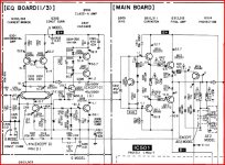
Here's a schematic of the power amp section
1. All resistors are correct as per values, but no voltage across emitter resistors. When this test is conducted, no load is connected - though connecting one makes very little difference. I see about 0.3-0.4mV across the resistor, not the expected few mV. The amp works OK though, and heats up properly when pushed hard. Where should I start looking?
2. Output transistors on one channel smoked (my fault, while trying to troubleshoot) - 2SA1492/2SC3856 Sankens. Is the 1943/5200 a good substitute? They seem OK except the physical size, the newer ones are much larger and the amp requires a bit of mechanical dexterity to fit these properly, which I should be able to work out. Do the Toshiba devices have insulated bolt-holes? The originals did, and there's not much room for a bush in there.
3. The entire resistor compliment of the output section has been changed - it seems almost all the fusible resistors in the amp board fused at some point, so have been changed to some locally available carbon films. I suspect this will have some sonic impact, but the manual calls for 'fusible' resistors, I selected some Vishays (PPBCT series on Digikey). Would those work, or should I leave the current ones in?
Here's a schematic of the power amp section
An externally hosted image should be here but it was not working when we last tested it.
I spent some time troubleshooting, and it seems the faulty part is Q409/459. I've put in all the voltages at the suspect part of the amp - can someone confirm?
I replaced the output pair with 1943/5200 and it works well enough, sounds a little better than the originals to me...
I'm surprised the thing is still playing, apparently without any distress.
Thanks for the help.
And what would be a good substitute part? The specs say is is 200MHz, 140V, 200mA part with HFE ~300. NEC original, not available in my country. Since it's a CCS, can I get away with a slower device?
This is a slightly inferior device - Digi-Key - ZTX455-ND (Manufacturer - ZTX455).
This is the original part: 2SC3514 pdf, 2SC3514 description, 2SC3514 datasheets, 2SC3514 view ::: ALLDATASHEET :::
I replaced the output pair with 1943/5200 and it works well enough, sounds a little better than the originals to me...
I'm surprised the thing is still playing, apparently without any distress.
Thanks for the help.
An externally hosted image should be here but it was not working when we last tested it.
And what would be a good substitute part? The specs say is is 200MHz, 140V, 200mA part with HFE ~300. NEC original, not available in my country. Since it's a CCS, can I get away with a slower device?
This is a slightly inferior device - Digi-Key - ZTX455-ND (Manufacturer - ZTX455).
This is the original part: 2SC3514 pdf, 2SC3514 description, 2SC3514 datasheets, 2SC3514 view ::: ALLDATASHEET :::
Last edited:
That would be Q411/461 in mine.
My problem part seems to be Q308 (your circuit). Q309 seems to be fine as there is a about 1.6V between emitter and collector, but I'll check again.
Q308 seems to be open circuit collector-emitter (no voltage at collector), but I don't know how to check this properly, in circuit or out. I'll try desoldering both and checking, may be I'll have to build a small rig for it?
If you are sure the amp plays OK with no audible distortion at very low levels then I would be careful and recheck your results. Using your circuit,
Check the voltage across R472, it should be around 0.7volts.
Does adjusting the bias pot not cause any increase in volts over the output emmiter resistors ? If not measure the voltage across C456 and see if it varies adjusting the bias pot.
Don't take too much notice of printed voltages... measure and confirm yourself that they are what you expect
The circuit shows 1.6 volts on emmiter of Q462 and 1.7v on the base for example which is wrong... the transistor would not be turned on at all like that.
Thanks Mooly, I'll do that once I finish off restoring my friend's Luxman L-1 later tonight, or maybe tomorrow.
Offhand I do remember that between the maximum and minimum pot position, the variation in the voltage across the emitter was 0.1mV - it would change from 0.2mV to 0.3mV. also, at very low levels there is a bit of crossover distortion, plainly audible if you listen hard enough - but my speakers are <87dB/W, so you've to listen really, really hard for it. Once it reaches normal listening levels, there is no issue.
Offhand I do remember that between the maximum and minimum pot position, the variation in the voltage across the emitter was 0.1mV - it would change from 0.2mV to 0.3mV. also, at very low levels there is a bit of crossover distortion, plainly audible if you listen hard enough - but my speakers are <87dB/W, so you've to listen really, really hard for it. Once it reaches normal listening levels, there is no issue.
Check the above first... that volt drop across R472 and also check (measure ohms) R472
Wondering if someone has put wrong values in 1K instead of 100 ohm etc. Worth measuring them all around there, the values are all low enough to measure in circuit I would think.
I would expect audible distortion with no bias. The pot should swing it fairly high.
If the transistor is OK (Q461) and everything else is OK it has to be either a duff or incorrect value in the chain of components R474 D456 D457 R475 and the pot or unlikely C456 short circuit.
Well well welll.
R472 reads 100 ohms, and is showing a stable voltage drop of .65V.
The values of the resistors are all correct, the first thing I did when I got the schematic was to check that the new parts matched the values in the datasheet.
Funnily, that R472 never got replaced, it was the only fusible resistor that is still original in the entire diagram. I'll pull out Q411/461 for testing out of circuit, it's heatsink mounted so should be simple enough.
I'll look at all the parts you suggested and report back tomorrow evening (it's nearly midnight here). Thanks a lot for helping out - this was becoming a solo journey till you showed up, so really appreciate the assistance.
Another question is, should I worry too much about it? I have no major issues apart from a low-level distortion issue, and *very* cold heatsinks. What is the worst that could happen? Specially seeing that the parts are so ancient, and getting replacements are impossible...
I just rewired a Luxman L1 with the same large Toshibas and Panasonic caps, but if any of the small signal stuff blows, not a chance I'll ever find it. This is a more recent amp, but it doesn't look like anyone has *any* of the parts in stock, except some obscure sources I don't know I can trust...
R472 reads 100 ohms, and is showing a stable voltage drop of .65V.
The values of the resistors are all correct, the first thing I did when I got the schematic was to check that the new parts matched the values in the datasheet.
Funnily, that R472 never got replaced, it was the only fusible resistor that is still original in the entire diagram. I'll pull out Q411/461 for testing out of circuit, it's heatsink mounted so should be simple enough.
I'll look at all the parts you suggested and report back tomorrow evening (it's nearly midnight here
). Thanks a lot for helping out - this was becoming a solo journey till you showed up, so really appreciate the assistance.Another question is, should I worry too much about it? I have no major issues apart from a low-level distortion issue, and *very* cold heatsinks. What is the worst that could happen? Specially seeing that the parts are so ancient, and getting replacements are impossible...
I just rewired a Luxman L1 with the same large Toshibas and Panasonic caps, but if any of the small signal stuff blows, not a chance I'll ever find it. This is a more recent amp, but it doesn't look like anyone has *any* of the parts in stock, except some obscure sources I don't know I can trust...
You're welcome
.65 across 100 ohms means the current through the vbe multiplier is correct. It's mounted on the heatsink just to sense the temperature and provide thermal compensation... to avoid thermal runaway.
Check those components I mentioned before in the bias generator, and also check that D456 and D457 each have 0.7volts or so across them when it's on. It's so unusual for that part of the circuit to be faulty in any amp.
The harder Q411 is on, the less voltage is across it, and that means less bias. As you turn the pot (to increase bias) you are actually turning off Q411 so it starts to develop voltage across it. As that rises the outputs then start to conduct.
So the fact the amp works, but just has this problem means it has to be something simple.
With your meter on DC volts does the voltage across Q461 vary and if so between what limits. It should go down to near zero at min bias and as high as 3.5 volts or so at which point the outputs should be getting very hot.
Also check the 0.1 ohm resistors, that they are OK and not been shorted out by anyone with a wire link etc.
Are both channels the same ? if so it suggests a man made fault... incorrect vlue somewhere. Is the pot the correct value ?
Here goes:
R472 is A-OK, showing the correct drop in voltage, which means Q459 is turned on.
Assuming one needs 3.2-3.5V between the bases of Q462/463 for the output stage (three Vbe drops per side) to be turned on. One sees only 1.2V, and the base of Q463 idles slightly positive (turned off). When the volume increases, one can see the transistor turn on - both the base and emitter voltages turn negative.
With the turning of the pot, there seems to be absolutely no difference in the base voltage of Q461 at all - about 20mV, and even that I can't be sure of. the diodes seem fine, showing 1.1-1.2V drop across the combination and 550-600mV each.
The collapse seems to be around Q455/456. I don't know the terms used to describe that pair of transistors - cascode? Anyway by my reckoning the collector of Q456 should be ~2V, it is roughly 1V, give or take. The other side of the equation is Q459 should be around -1.5V, it is basically 0V.
Anyway I think the amplifier's idling point is somehow set by this Q455/456 pair and Q459/R463/C456 combination, and Q414 is the control mechanism for thermal tracking.
Prime suspects are still Q459, Q455/456 and Q461 - first two/three open-circuit, last one short-circuit. Little difficult to believe amp is working as the only path for the audio signal is through Q455 and 456. Board looks untouched (no resoldering at all) apart from the 7 fusible resistors per channel that have been replaced, and one of those is in the emitters of Q455/456, so I am beginning to think the original fault occurred somewhere in that area. What would be the actual function of that pair? Both channels are identical in measurements.
As of now I don't really know what else to do apart from pulling all the above and checking them.
Last edited:
Here goes:
R472 is A-OK, showing the correct drop in voltage, which means Q459 is turned on.
That's correct
Assuming one needs 3.2-3.5V between the bases of Q462/463 for the output stage (three Vbe drops per side) to be turned on. One sees only 1.2V, and the base of Q463 idles slightly positive (turned off). When the volume increases, one can see the transistor turn on - both the base and emitter voltages turn negative.
That's right, you have to measure between the bases.
With the turning of the pot, there seems to be absolutely no difference in the base voltage of Q461 at all - about 20mV, and even that I can't be sure of. the diodes seem fine, showing 1.1-1.2V drop across the combination and 550-600mV each.
This is the vital clue... does the voltage ACROSS C456 increase as you turn the pot ? You say Q461 short ???? measure it out of circuit. What is the Base Emmiter volt drop of Q461 as you turn the pot, that's a massive clue
The collapse seems to be around Q455/456. I don't know the terms used to describe that pair of transistors - cascode? Anyway by my reckoning the collector of Q456 should be ~2V, it is roughly 1V, give or take. The other side of the equation is Q459 should be around -1.5V, it is basically 0V.
Anyway I think the amplifier's idling point is somehow set by this Q455/456 pair and Q459/R463/C456 combination, and Q414 is the control mechanism for thermal tracking.
Prime suspects are still Q459, Q455/456 and Q461 - first two/three open-circuit, last one short-circuit. Little difficult to believe amp is working as the only path for the audio signal is through Q455 and 456. Board looks untouched (no resoldering at all) apart from the 7 fusible resistors per channel that have been replaced, and one of those is in the emitters of Q455/456, so I am beginning to think the original fault occurred somewhere in that area. What would be the actual function of that pair? Both channels are identical in measurements.
As of now I don't really know what else to do apart from pulling all the above and checking them.
I'll look in again in couple of hours.
As BOTH channels the same it really points to some man made fault like a wrong value fitted somewhere ?
Q455 is the VAS stage cascoded with Q456... a typical Sony ellaboration
The current through R472 means the vbe generator should be able to provide the required bias for the outputs whether anything before that is faulty or not.
I would be tempted to run it with a 100 watt bulb in series with the mains during faultfinding just to be sure in case anything goes wrong.
If you do that, you could remove Q461 completely and add a 1k pot across C456 in place of the transistor and starting with the pot at MINIMUM resistance slowly turn and see if outputs conduct... bulb will light.
Got it - this is Sunday faultfinding for me.
I have other woes though - One of the driver transistors is showing a B-E short, I cleaned the PCB and measured everything and this seems to be completely toasted. I will have to first get the transistors in before further work can be done. I don't know if it was always like this - it is on the channel that I inadvertently blew in my initial faultfinding (where I blew the output pair). The other channel seems to be fine.
Edit: I did measure the B-E drop on Q461. It was around .3V, not changing at all as the pot turned... I will measure again once I get this animal up and running.
Remember you MUST check transistors out of circuit. Even a few millivolts residual charge upsets a DVM giving false readings.
If you power up without the VBE multiplier in circuit (Q461) than the outputs will conduct (should conduct) probably destructively... hence the bulb recommendation.
Which is showing a B-E short ? Is that measured in circuit ?
If you power up without the VBE multiplier in circuit (Q461) than the outputs will conduct (should conduct
) probably destructively... hence the bulb recommendation.Which is showing a B-E short ? Is that measured in circuit ?
Q464 is showing B-E short both in and out of circuit. It must have got fried with the output pair. Normally the supply caps for the output stage would be drained at the same rate as the preamp stage, but due to no bias they hold full charge after turn off (separate supplies - hindsight is 20/20). A single slip did the output pair in (shorted -ve supply to emitter of the NPN output transistor) and I did not check all the transistors at that time, only after giving a board a thorough going-over today I was able to spot the short in the B-E junction of the NPN driver. Both the original output pair were showing C-E shorts, and the amp was blowing fuses - after replacing it was playing so I thought that was that.
The other channel measures OK. Both channels were playing, but the defective channel was sounding very different for some reason, probably because only one output transistor was ever switched on Cheap Class A .
I will be trying to use 2SC5171/A1930 Toshiba pairs as drivers now (if I find them), they're the closest I could find to the obsolete 2275/985 NECs used here, with slightly higher Cob - hopefully they will work. I will also be checking the rest of the transistors and all voltages on Sunday to reconfirm all readings and whether all parts are intact. Once again, thanks for the help - much appreciated. I will recheck around Q461 - would you recommend I use a 3.3V zener (or a couple of LEDs) instead of the transistor? Will that help hold a maximum difference between the pre-drivers to the right value? Should I swap in a known good BD139 (close enough, slightly lower Vce) for Q461 and check if it fixes the bias?
I will be constructing a light bulb tester as well, I've also a large stock of fuses. I blew out the originals when the first pair toasted.
The other channel measures OK. Both channels were playing, but the defective channel was sounding very different for some reason, probably because only one output transistor was ever switched on
Cheap Class A .I will be trying to use 2SC5171/A1930 Toshiba pairs as drivers now (if I find them), they're the closest I could find to the obsolete 2275/985 NECs used here, with slightly higher Cob - hopefully they will work. I will also be checking the rest of the transistors and all voltages on Sunday to reconfirm all readings and whether all parts are intact. Once again, thanks for the help - much appreciated. I will recheck around Q461 - would you recommend I use a 3.3V zener (or a couple of LEDs) instead of the transistor? Will that help hold a maximum difference between the pre-drivers to the right value? Should I swap in a known good BD139 (close enough, slightly lower Vce) for Q461 and check if it fixes the bias?
I will be constructing a light bulb tester as well, I've also a large stock of fuses. I blew out the originals when the first pair toasted.
Very strange fault having Q464 short yet the amp still plays.
A BD139 (that's a golden oldie) is fine, it's not even in the audio path as such. It never sees more than a few volts across it. Make sure it's isolated electrically from the heatsink, don't know if the 2SD414 was all plastic or not.
I mentioned fitting a pot etc only as means of eliminating the vbe multiplier for faultfinding... you would never get the bias stable enough for real use without Q461... it is vital
The 2SC/2SA should be fine too... but do use a bulb to power it up first. If something was amiss and the new Q461 wasn't turned on then the outputs would probably get zapped before you realised what was happening.
- Status
- This old topic is closed. If you want to reopen this topic, contact a moderator using the "Report Post" button.
- Home
- Amplifiers
- Solid State
- Sony TA-F222ES, need help