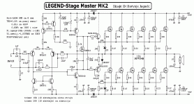
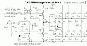
Hi all, What modifications are needed to drive this nice amplifier with +/-50V rails ?
An externally hosted image should be here but it was not working when we last tested it.
Attachments
Hmmmm... It would probably be OK with only 2 or 3 output devices per side (i.e. 4 or 6 IRF240 total). You could use 60, 75 or 80 volt capacitors (not 100v) to save some money. Otherwise most of the rest will probably be OK with 50 volt rails. You should get at least 100 watts/ch into 8 ohms with +/- 50 volt supplies.
But I am not sure the design is the best choice? One of Randy Slone's MOSFET designs probably would perform better. But, better still, check out the LME49830 at http://national.com. There is an application note for a very simple amp that will work very well with 50 volt rails and perform MUCH better than the design in your diagram. Your design claims THD 0.18% while the National design runs 0.003% under most conditions and a maximum of 0.01% worst case with full power at 20 Khz.
The LME49830 amp will also be easier to build, cost less and likely sound better. There is much information here on diyaudio about the LME498xx series of parts such as:
LME498xx Thread
The National reference design uses the same IRFP240 in a complimentary configuration. Another, even less expensive, option is the National LM4702 stereo IC. You can also buy kits and ready-made amplifier modules using the LME49830 and LM4702 from Asian sources for very low cost such as those sold by panson_hk here on diyAudio and several vendors on eBay have LM4702 designs for sale.
It should run ok with +/-50 volts.
You would then not need as many output transistors.
Use 3 pairs of IRFP250. They are £1-50 each from RS Components www.rswww.com
You would then not need as many output transistors.
Use 3 pairs of IRFP250. They are £1-50 each from RS Components www.rswww.com
Ermac said:I'll use 12 IRFP250, because I want to use a 2 ohms driver to get the same power(350-500W).
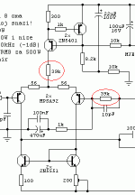
As I saw the Quasi's similar designs, the two circled resistors shown in the below pic need to be lowered. But to what values in this design?
The left resistor can be divided by 2.
The right resistor can be divided by 2 as well.
I dont use the left resistor at all in my designs.
The right resistor sets the gain of the amplifier to 39k/1k which is 39. If your only using half the supply voltage then the gain should be half as much so make the 39K into 18K.
The left resistor can be divided by 2. The right resistor can be divided by 2 as well.
Yes it can.... BUT , that will double the unity gain point of the amp and at that frequency you will have an insufficient phase margin (possible oscillation). If you continue further and degenerate the LTP (the 2 56R's) further (use 100- 120R instead) , the amp will again have a @800K unity gain and >80 deg. phase margin.
As far as the 2nd- 39k resistor, the one that is not GNFB , it is current source related (one at "tail"). OS
Let me make certain I understand you correctly. My understanding is that I should divide the circled resistors by 2 and then use 120R resistors instead of the 56R's.
The 10pF cap across the FB resistor should not be increased to 22pF? (to get the same TC as we decrease the resistor to 18k?)
The 10pF cap across the FB resistor should not be increased to 22pF? (to get the same TC as we decrease the resistor to 18k?)
Let me make certain I understand you correctly. My understanding is that I should divide the circled resistors by 2 and then use 120R resistors instead of the 56R's.
I won't do all the work... you should download LTspice -http://www.linear.com/designtools/software/ltspice.jsp and build the circuit. I just did your proposed changes to my "FA1" , which is just your standard current mirrored douglas self amp , and conveyed the results. The 10pf "lead compensation" cap can even be omitted with the right VAS trannies and miller cap.
If you use good transistor models ,"cause and effect" becomes quite apparent with simulation. How it sounds is another matter...
OS
EDIT: My main point is that when you change one aspect (amps total gain) , you inversely change other aspects (UG - open loop gain ,etc.)
the front end currents are all supplied by CCS.
You do not need to change anything to reduce the supply voltage to +-50Vdc.
Don't change the gain unless you can thoroughly check you have no oscillation and good square wave performance in the built amplifier.
The 39k resistor in the tail of the LTP, when fitted, usually drops about half the rail voltage. i.e. about 40V in the +-95Vdc design and about 25V for your proposed +-50Vdc. 12k would drop ~24V with 2mA tail current.
Well, thank you! I won't change any resistor.
I'll use 2SC669/2SB649 instead of MJE340/MJE350.
Which one is suitable as a substitute of the following transistors?
IRF510: IRF540? or IRF630? or IRF640? or IRF730? or IRF740? or IRF840?
MJE15034: TIP41? or 2SC669?
MJE15035: TIP42? or 2SB649?
I'll use 2SC669/2SB649 instead of MJE340/MJE350.
Which one is suitable as a substitute of the following transistors?
IRF510: IRF540? or IRF630? or IRF640? or IRF730? or IRF740? or IRF840?
MJE15034: TIP41? or 2SC669?
MJE15035: TIP42? or 2SB649?
Attachments
Ermac said:I'll use 12 IRFP250, because I want to use a 2 ohms driver to get the same power(350-500W).
As I saw the Quasi's similar designs, the two circled resistors shown in the below pic need to be lowered. But to what values in this design?
ermac, those 2 39k resistors haave nothing to do with with each other....basically...
the one on the ltp takes away most of the heat from the ccs transistor, and the other one on the right sets the gain of the amp...it should stay the same even as you scale down your rails.
realize that scaling down the rails to +/-50 volts or so lowers your available power to about 100watts at 8 ohms...
this is just the first half of the story, the second half is your power supply, just how big and robust your power supply is will tell just how much power you can get at 2 ohms...
until we see your complete amp, it is hard to tell really...
looking at the +/-95 rails, this amp is goo for about 300watt/8ohm, that is if your transformer does not sag big time...
- Status
- This old topic is closed. If you want to reopen this topic, contact a moderator using the "Report Post" button.
- Home
- Amplifiers
- Solid State
- "LEGEND" 500W RMS Modification


