I have read the follow articles:
- Discrete AD797 up and running
http://www.diyaudio.com/forums/showthread.php?s=&threadid=135637
- Help with improved Wilson current mirror (AD829)
http://www.diyaudio.com/forums/showthread.php?threadid=134019
- Folded cascode headphone amp (AD829, AD797 and LT1469)
http://www.diyaudio.com/forums/showthread.php?s=&threadid=124122
- AD 797
http://www.diyaudio.com/forums/showthread.php?threadid=135637&perpage=25&pagenumber=1
original Datasheet (schematic page 11):
http://www.analog.com/static/imported-files/data_sheets/AD797.pdf
then I looked by "circuitmaker" at some relationships between circuit variations and THD at low and high frequencies. At bottom the results - but please note, that is not really an AD797, because quiescent current is much more higher (quiescent current 90mA instead 8-10mA). There are no discrete bjt transistors on the marked with high ft and low current at the same time. Please note secondly follow: by this simulation all capacitors and resistors so as the voltage source (power supply) and input source (signal generator) are idealized (i. e. no internal resistance by the power supply). In additional there are no lead respective wire inductance and spread capacitance through PCB layout.
Only the effects of pure circuit - are to see.
In real life (few years ago) only the versions IV and VI (only BUF) I have tested (I have implement in commercial phono- pre- and power amps with bad sound) - so beginners should not be evaluate and not trying for diy.
Following parameters are valid for all versions:
Voltage gain = 10-times, input 1Vss, output 10Vss, wave form: sine wave.
All PDF images are directly comparable, after performing download of all pdf files.
Follow trend is to be noted that when decreasing circuit complexity the THD at high frequencies goes down and at low frequencies the THD values increase. Additional it is clearly to see by freqency-response without caps for compensation, that the nearly perfect circuit pcb layout is very hard to find (which cad software therefore there are on the marked- perhaps one of you knows more?).
Also of interest it could be, whether there are great differences by simulation results in other cad software (e.g. Orcad, Microsim or others). Perhaps one of you this one can check out.
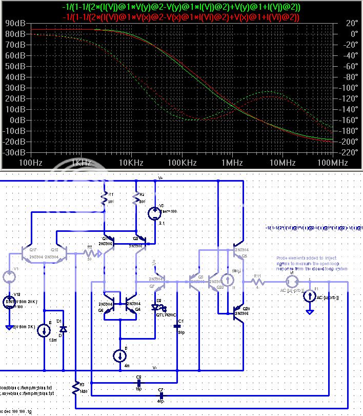
A: AD-797, close by orig. circuit from datasheet page 11 - simulation results
1) AC Analysis (Frequency response) without Cc and Cn
2) AC Analysis (Frequency response) Cc: 220p/390 and Cn 220p/390
3) Transient Analysis 10 KHz (sine wave)
4) Fourier Analysis 10 KHz (THD)
5) Transient Analysis 200 KHz (destroyed sine wave)
6) Fourier Analysis 200 KHz (THD)
1) AC Analysis (Frequency response) without Cc and Cn
2) AC Analysis (Frequency response) Cc: 220p/390 and Cn 220p/390
3) Transient Analysis 10 KHz (sine wave)
4) Fourier Analysis 10 KHz (THD)
5) Transient Analysis 200 KHz (destroyed sine wave)
6) Fourier Analysis 200 KHz (THD)
Attachments
AD797 discrete clone - comparison of seven variations Continued
B AD-797 Var I (without Q12) - simulation results
1) AC Analysis (Frequency response) without Cc and Cn
2) AC Analysis (Frequency response) Cc: 70p/500 and Cn 20p/1K5
3) Transient Analysis 10 KHz (sine wave)
4) Fourier Analysis 10 KHz (THD)
5) Transient Analysis 200 KHz (sine wave)
6) Fourier Analysis 200 KHz (THD) K2: 1mV K3: 3mV
Attachments
AD797 discrete clone - comparison of seven variations Continued
C: AD-797 Var II (without Q12 and I7) - simulation results
1) AC Analysis (Frequency response) without Cc and Cn
2) AC Analysis (Frequency response) Cc: 70p/500 and Cn 20p/1K5
3) Transient Analysis 10 KHz (sine wave)
4) Fourier Analysis 10 KHz (THD)
5) Transient Analysis 200 KHz (sine wave)
6) Fourier Analysis 200 KHz (THD) K2: 1mV K3: 3mV
Attachments
AD797 discrete clone - comparison of seven variations Continued
D: AD-797 Var III (2xCurrent source instead Current mirror Q5/Q6, without Q12 and I7) - simulation results
1) AC Analysis (Frequency response) without Cc and Cn
2) AC Analysis (Frequency response) Cc: 47pF/1K, without Cn
3) Transient Analysis 10 KHz (sine wave)
4) Fourier Analysis 10 KHz (THD)
5) Transient Analysis 200 KHz (sine wave)
6) Fourier Analysis 200 KHz (THD) K2: 3mV K3: 4mV
Attachments
AD797 discrete clone - comparison of seven variations Continued
E: AD-797 Var IV (1xCurrent source instead Current mirror Q5/Q6 Q12 and I7) - simulation results
1) AC Analysis (Frequency response) without Cc and Cn
2) AC Analysis (Frequency response) Cc: 33pF/1K, without Cn
3) Transient Analysis 10 KHz (sine wave)
4) Fourier Analysis 10 KHz (THD)
5) Transient Analysis 200 KHz (sine wave)
6) Fourier Analysis 200 KHz (THD) K2: 0,75mV K3: 1,25mV
Attachments
AD797 discrete clone - comparison of seven variations Continued
F: AD-797 Var V (resistor instead Current mirror Q5/Q6 Q12 and I7) - simulation results
1) AC Analysis (Frequency response) without Cc and Cn
2) AC Analysis (Frequency response) Cc: 0,8pF new place, without Cn
3) Transient Analysis 10 KHz (sine wave)
4) Fourier Analysis 10 KHz (THD) K3: 20mV
5) Transient Analysis 200 KHz (sine wave)
6) Fourier Analysis 200 KHz (THD) K3: 20mV
Attachments
AD797 discrete clone - comparison of seven variations Continued
G: AD-797 Var VI only buffer stage - simulation results
1) AC Analysis (Frequency response) without Cc and Cn
2) AC Analysis (Frequency response) Cc: 100pF new place, not use for 3) until 6)
3) Transient Analysis 200 KHz (sine wave)
4) Fourier Analysis 200 KHz (THD) no distortion by 10KHz
5) Transient Analysis 10 MHz (sine wave)
6) Fourier Analysis 10 MHz (THD) K2: 3,6mV K3: 2,5mV
Attachments
Hi,
I noticed that the spectrum displays have a linear vertical scale rather than the ususal log scale in dB. The linear scale makes it quite hard to compare curves and to appreciate the actual performance. Would it be possible to change those scales to log?
jd
I noticed that the spectrum displays have a linear vertical scale rather than the ususal log scale in dB. The linear scale makes it quite hard to compare curves and to appreciate the actual performance. Would it be possible to change those scales to log?
jd
Hi, I use LTSpice for simuation. The result is close to real life. My "AD797" is still up and running and performs well.
andy_c said:Hi,
There's more detail of the AD797 implementation available too. For example, see this post. That schematic was based on the one from Scott's AES article on the AD797, which has lots more detail than the datasheet has. For more information on that AES article, feel free to email me.
That schematic was our actual working one at one point. if you read the posts around that link we corrected a couple of misprints in values in that discussion. Most of the original files did not make the translation from VAX to Sun's.
some simplified ad797 sim "results"
I think I've shown an explaination for at least one issue with Class AB operation of the ad797:
http://www.diyaudio.com/forums/showthread.php?s=&postid=1809194&highlight=#post1809194
Class A bias of the discrete output as you show or a buffer should be a basic requirement for low distortion amplification
http://www.diyaudio.com/forums/showthread.php?s=&postid=1813250&highlight=#post1813250
also as I recall I couldn't get good result from the mirror bootstrap without adding a little more Vdrop to the bootstrap buffer (the LED in my schematic)
so jcx, is this a worthwhile project/upgrade? I absolutely LOVE AD797, its my favorite chip, I use it with a dicsrete diamond buffered output but would love to build this up and have a totally discrete circuit on the output of my dac. I like tweaking and building for the sake of knowing you can as well, but in this instance i'm actually looking for audible improvement over the IC
jcx's and andy_c links all go to the Blowtorch preamp thread and nothing on the AD797.
Anyone know what's going on?
This one seems to work:
https://www.diyaudio.com/forums/solid-state/123613-class-biasing-ad797-6.html#post1525757
Anyone know what's going on?
This one seems to work:
https://www.diyaudio.com/forums/solid-state/123613-class-biasing-ad797-6.html#post1525757
Last edited:
Wouldn't ZTX851's be the appropriate input devices for a very low voltage noise circuit, rather than BC547C's?
The luxury of 10µF's scattered through the circuit is not very true to the original 🙂
The luxury of 10µF's scattered through the circuit is not very true to the original 🙂
What kind of Rbb' do BC547Cs have anyway? More than ~25 ohms, I suspect, possibly in the hundreds of ohms like BC550s - a typical noise figure of 2.0 dB at Rs = 2 kOhm (ON Semi) is not promising, indicating ~1 kOhm. Going by the table in AoE 3rd, p. 500-odd, you are better off choosing just about anything else.Wouldn't ZTX851's be the appropriate input devices for a very low voltage noise circuit, rather than BC547C's?
Now that would be some advances in semiconductor manufacturing. 😉The luxury of 10µF's scattered through the circuit is not very true to the original 🙂
#discretesareunderrated
- Status
- Not open for further replies.
- Home
- Amplifiers
- Solid State
- AD797 discrete clone - comparison of seven variations