often when we do upgrades we replace capacitors with more exotic parts ....
for example the input cap of one amlifier is 4.7 mfd/63volt electrolytic and we like to replace that with 4.7mfd MKT if the size fits
now there is somewhere in the forum a note regarding exotic parts that due to size often behave like antenas and either polute the area of the amplifier with signals or pick up signals from the amplifier or cables etch etch.
if we accept this theory as correct how would be an idea to use a 4.7mfd / 100n mkt in the input but cover it with copper shelf adhesive film and then connect a lead from the shielding to ground....
something like a ground plane for componends .....
seen it made like that in a teac cd player
any opinions ???
My way to reduse noize
Hi Sakis
I always do the following to reduse noise to below the noize floor:
1. a 10 ohm resistor between smallsignal input and feedback gnd to power gnd.
2. Input from pre amp or sounce flouting.
3. Connect the star point grnd point from the center of the capacitors.
4. Keep the rectifier closest to the transformer.
5. I relay most of the power supply noise on the PSRR caps.
6. Shielding on input small signal wiring.
7. I use a common star ground.
So far on the 20 amps that I have made this has always worked for me.
I have seen many old amps with double sided pcb and component side used as shield. Some comments that I have heard were related to capacitance created between ground and pcb tracks when doing this.
So far all amps were quiet
Chris
Hej sakis
I can only see that this cap replacement can cause a problem in "normal" enclosed hifi equipment if you have unshielded high power wiring crossing the input circuit. With RF amplifiers it can be a problem, but not with the kind of gear we build, unless we have to place sensitive input circuits near power circuits.
If it do pickup more noise, there was a problem allready from the very beginning with electrolytic cap. As taj points out, the metal chassis should take care of outside radiated noise.
For the inside radiated noise, bad placement of power wiring in a chassis (crossing close by the input circuit) can cause some noise though. I often see both input and output wiring crossing the chassis in a way to minimize the lenght of the cables, placing them very close to each other (if not routed together)
Separate the wires, not neccessary for the shortest way but for the most noiseless way (low signal wires near low signal circuits and power wires near power circuits. Remember shielded cables are not very sensitive to small level radiated noise.
It doesn't matter if your low signal wiring gets a few inch's longer, if it then can be routed in a "noise safe" area.
Regarding the Teac CD player you have seen, this looks to me that they either first experienced this problem after production was started, or that they had to place this circuit close to other circuits. The shielding of the circuit goes both way. It could be that the circuit needed protection from radiated noise, or it could be that the circuit it self generated noise, and was shielded to protect nearby circuits.
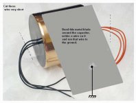
Cut a thin foil of copper or this tiny sheet of metal used to make can for food
Put it around those enormous capacitors used into the input...those non polarized big ones..them solder a wire and run it to the ground.
This will reduce the component behave alike a pick up antenna...will reduce, but will never stop entirelly.
Enormous mass.... too much material to absorb magnetic energy and transform it into electricity.
Those enormous capacitors are a problem... in special the ones used into the input.
That worry, about magnetic pickup, makes sense to me, as i have worked into Radio Frequency transmitters and i have measured, several times, induced radio frequency and also induced magnetic fiel from nearby transformers..this happens.
Carlos
Attachments
Use a high value low voltage electrolytic, that will fit and will behave like a plain short circuit even at the lowest audio frequencies. The only problem that I have seen with electrolytics is a reduction of capacitance at low frequencies leading to higher than expected LF group delay and roll-off points, but a higher value solves that.
Those huge rolled-film capacitors are junk, they are microphonic and they pick up both all magnetic and electric stray fields when used for small signals, and ccopper shielding is only effective for the latter, not to mention that it adds parasitic capacitance to ground. They are mostly useful for speaker passive crossovers only.
They are a good snake-oil business too...
High value SMD chip ceramics are becoming another alternative for serious AC coupling. They are somewhat non linear, but higher values are now available, like 100uF 4V in 1206, high enough to appear as a short circuit at the frequencies of interest.
- Status
- This old topic is closed. If you want to reopen this topic, contact a moderator using the "Report Post" button.
- Home
- Amplifiers
- Solid State
- Shielding .....