so you trust onsemi s datasheets, but not the models they publicly
deliver?..seems bad faith to me..
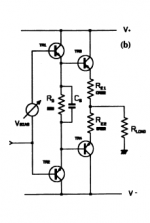
what is measured by the circuit is the ac voltage gain with a constant
transconductance..
if you prefer, fixed transconductance and variable frequency...
have you an explanation other than the easy one that is to blame the
models wich i said it ad nauseam are those of the manufacturers...
At this point, all I can say is that you need a good lecture on device models and device parameter extraction. Eventually, you may get some clarity on how these devices are working, how parameters are modelled and measured.
BTW, transconductance # Beta.
At this point, all I can say is that you need a good lecture on device models and device parameter extraction. Eventually, you may get some clarity on how these devices are working, how parameters are modelled and measured.
BTW, transconductance # Beta.
my point is that onsemi may have the same Ft at 1MHZ, but at higher frequencies, the Ft of the toshiba is better...
since then, i did at least brought some sims while your only answer is to ressort to theory that is well known in the goal of eluding the question and trying to brand the other as uncompetent and lacking knowledge..
your last post make no exception..
You can do it this way, old ,well known.. Base can be bias in reverse polarity (if needed), and available currrent is limited only by driver current (e.g 8A for MJE15031/15032). So speedy enough, and measurements show it, e.g. limitatition behaviour at 10kHz (no evidence of "sticking" in limitation), fast recovery.They are always an issue. The beautiful measurements don`t show that either.
Attachments
?????count on longer turn-off time for the Darlington pair than for a single device
Toshiba's 30 year old transistors looked better.
Actually, taking a close look at the datasheets, 2SC5949 and the old 2SC3281 only differ by thermal resistance.
") All other parameters are the same. I'd guess 2SC5949 is the 2SC3281 die with the solder thickness improvement of the 2SC5200-generation devices.
All other parameters are the same. I'd guess 2SC5949 is the 2SC3281 die with the solder thickness improvement of the 2SC5200-generation devices.Greatly reducing the signal-to-noise ratio of the thread; your simulation does not measure fT. Moreover, the parameter fT does, by definition, not vary with frequency. What Bob and syn08 wrote is correct.since then, i did at least brought some sims
Last edited:
my point is that onsemi may have the same Ft at 1MHZ, but at higher frequencies, the Ft of the toshiba is better...
since then, i did at least brought some sims while your only answer is to ressort to theory that is well known in the goal of eluding the question and trying to brand the other as uncompetent and lacking knowledge..
your last post make no exception..
Again, your point is incorrect. I think I explained above what is the meaning of (and how Ft is determined using) "Ft @ 1MHz".
For all practical purposes, there is no difference between "Ft @ 1MHz" and "Ft @ 2MHz".
Again, your point is incorrect. I think I explained above what is the meaning of (and how Ft is determined using) "Ft @ 1MHz".
For all practical purposes, there is no difference between "Ft @ 1MHz" and "Ft @ 2MHz".
i know as well as you what is the meaning of the Ft..
i didn t wait for you to understand..
you keep on your track of branding the other uncompetent..
the question is :
why two devices with the same Ft have (largely) different ac voltage
gain in a circuit that is designed to minimize the unequality of the devices
respective parasistic capacitances...
can you answer this by something else than talking about definitions
of devices parameters we are all aware of, at least in their local
solutions....
Piercarlo,
discharging the base takes time, precious time. It´s a slow-moving charge. No test needed.
Discharging base is needed only when bipolars saturate. When bipolars operate in linear region base charge don't need any discharge (if beta remain constant of course). Ft specification make sense ONLY in linear region, not during switching.
BTW, high Ft bipolars have lower discharging time (mainly because have lower rbb) but not so low as their high Ft may induce to think. 2N3772 (Ft of 200 kHz) has switching times only five time longer than of modern High Ft bipolars and this should be of adivice to be a bit cautious when evaluating bipolar's speed only on FT comparing basis.
Last but not least. If switching times are strongly depedent from source impedance, FT is mainly dependent only on internal transit and life time of minority carriers travelling in the base region, a parameter completely controlled by "inside" of bipolars (mainly doping levels and materials and, a bit, geometries). If wouldn't be so, bipolars would have the same high frequency behaviour of MOSFETs... but this don't happen.
Piercarlo
PS - Real advantage using high Ft bipolars come only when used in class A or "non-switching" circuits. When used in normal class AB output stages, their real speed is hardly limited by switching time of ouput devices, which at best are com prised between 0,1 and 0,5 us (they worse at low currents, the most crucial because fall in the crossover region of amplifier... which slow-down just while it should speed-up!). With this working situation REAL Fts in class AB output stages are, at best, not more than 10 MHz).
BTW: I have a complete Sanken catalog of power bipolars reputed suitable for audio amplifiiers.... but there is not a single datasheet which show the otherwise usual graphs that show switching times behaviour versus collector current. And in classic class AB output stages are these times that really count in defining their high frequency limits - especially when heavily (and dangerously) loaded, when often the output stage transistors "promote" their drivers - usually better provided in Ft and switching times - as EFFECTIVE output devices and "declass"itself as a simple current "pass-through" (over direct biased or not again turned off base emitter junctions) while frequency of signal go higher.
Merry Christmas to all!
Last edited:
so you trust onsemi s datasheets, but not the models they publicly
deliver?..seems bad faith to me..
No. Spice models are right for CIRCUITAL simulation (to be carefully evaluated by an experienced engineer however!), when simulating FTs or similars reguire PHYSICAL simulation, that spice models aren't able to provide (not in the extent needed for the integral evaluation of charged carriers trasport involved in transistor behaviours).
Piercarlo
i know as well as you what is the meaning of the Ft..
i didn t wait for you to understand..
you keep on your track of branding the other uncompetent..
the question is :
why two devices with the same Ft have (largely) different ac voltage
gain in a circuit that is designed to minimize the unequality of the devices
respective parasistic capacitances...
Apparently you don't. The AC voltage gain has little to nothing to do with Beta.
For any other answers and explanations you are, from now on, in Lumba's trustful hands.
Keep up the good work. It's how we all learn.I always try to post clearly and completely so that most people reading the forum can understand and learn something if they do not know it already. I always try to do this in a way that is not condescending.
Don't let them put you down. That conduct (put downs) is outwith Forum rules.
Last edited:
Thomas?but I'll only believe it if I test it myself and see it.
Last edited:
.
2N3772 (Ft of 200 kHz) has switching times only five time longer than of modern High Ft bipolars and this should be of adivice to be a bit cautious when evaluating bipolar's speed only on FT comparing basis.
Last but not least. If switching times are strongly depedent from source impedance, FT is mainly dependent only on internal transit and life time of minority carriers travelling in the base region, a parameter completely controlled by "inside" of bipolars (mainly doping levels and materials and, a bit, geometries). If wouldn't be so, bipolars would have the same high frequency behaviour of MOSFETs... but this don't happen.
Piercarlo
-)
that say it all..
so you trust onsemi s datasheets, but not the models they publicly
deliver?..seems bad faith to me..
Absolutely correct. I wish it were not so for the models, but it is. Moreover, don't blame a device as bad just because the SPICE model is poor. Onsemi are definitely not the only ones whose SPICE models leave a lot to be desired.
I continue to believe that the way you are simulating ft is wrong.
Merry Christmas,
Bob
You can do it this way, old ,well known.. Base can be bias in reverse polarity (if needed), and available currrent is limited only by driver current (e.g 8A for MJE15031/15032). So speedy enough, and measurements show it, e.g. limitatition behaviour at 10kHz (no evidence of "sticking" in limitation), fast recovery.
Yes, the capacitor to help suck-out current is an old and well-known trick. However, consider how big the capacitor needs to be in order to be really effective. You will often find that it needs to be an electrolytic. I have never liked having to resort to this trick, and instead run the drivers hotter AND use devices with higher ft. Maybe some others here would like to comment on their feelings and experiences with this trick.
Merry Christmas,
Bob
Discharging base is needed only when bipolars saturate. When bipolars operate in linear region base charge don't need any discharge (if beta remain constant of course).
Way wrong. Look at the earlier comments on this topic in the thread.
Merry Christmas,
Bob
Mr. Cordell,
I am using resistor between bases of output transistors in order 33-47 ohm, so drivers are running at higher bias. With paralel capacitor about 1uF it performs quite well, this capacity seems to be enough. It is needed (in real life, not in testing with 100kHz square at full power) only at short ,fast transients, so here is a lot of time to discharge. This metod seems to me not so expensive (faster power devices with the same SOAR and Pd= more pieces and expensive device), and results are about the same. No crosconduction problems with "slow" MJL , power bandwith to about 200kHz, quite good DIM 100 and IMD19+20 results. Runnig drivers in A class or very near this (e.g resistors to opposite rails) brings (according my experiences) no advantages and improvement.
And I am always measuring performance (whole amplifier) also without load, at different levels and frequencies, to discover what really is caused by output devices.
Last edited:
Yes, the capacitor to help suck-out current is an old and well-known trick. However, consider how big the capacitor needs to be in order to be really effective. You will often find that it needs to be an electrolytic. I have never liked having to resort to this trick, and instead run the drivers hotter AND use devices with higher ft. Maybe some others here would like to comment on their feelings and experiences with this trick.
Merry Christmas,
Bob
When you use high fT output devices you generally will also need base stopper resistors and these will severely limit the peak base "suck-out" current, mitigating the advantage to some degree. Suppose you have a crossover region of 2V and 4.7 ohm base stoppers - 2/4.7 = 425mA.
The capacitor trick across the driver bias resistor is much more effective on low fT output stages that can get away without base stopper because of this.
Also, running the drivers hot just doesn't work very well when driving multiple parallel output pairs. Suppose you have a driver bias resistor of 10 ohms, giving a standing bias current of around 130mA. That can be considered reasonably hot.
Suppose the signal voltage is swinging in the negative direction, through the zero crossover. The NPN driver transistor will begin to turn off and the suck-out base current for the NPN power transistor will be provided by the PNP driver transistor, through that 10 ohm resistor.
That 10 ohm resistor ensures that the PNP driver cannot deliver a huge suck-out current. The only real cure here is to bypass it by a big cap, which is simple and effective.
Last edited:
- Home
- Amplifiers
- Solid State
- bipolar (BJT) transistor families for audio power output stages