Hi at all.
I am trying to make this amplifier. I channel is under test, but I have a problem that can't explain. Averything works fine, it's also playng in this moment and I have to sey that sound seems much better than I expected, but there is a big problem . With the scope I have seen the sin wave at 1 Khz, to be clipped at +- 11V.
Rail ar +/- 41 Vcc.
Could someone give me an idea of why this happens?
Thanks at all
An externally hosted image should be here but it was not working when we last tested it.
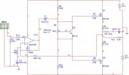
The local AC gain is 21 (26,4 dB), the global AC gain is 22 (26,8 dB).pro said:I don't know what you mean. The local gain is 26 db that is the same of the global. The offset at the exit is about 30 mV.
For the local feedback around the LM3886 the gain is R24+1/(C1*2*PI*f)+R17/R17. 1/(C1*2*PI*f) becomes infinity for DC, which makes the DC gain also infinity. Only thanks to R1 you don't get DC with nearly rail voltage at the output.
So the local DC gain is infinity and the global DC gain = global AC gain is 22.
What does that mean? For DC only the global feedback is relevant. For AC you force the voltage differential between the LM3886's output pin and the amplifier output to be 1/22 of the output voltage. Is that stable across the entire voltage range of the amplifier from 0 to full output swing?
E. g. for an output swing of 22 V there would be 1 V across R1 and either across R21+M2+R5 or across (R13+R3+R7||Q1||C4)+R6+M1+R4. For an output swing of 11 V there would only be 0,5 V. For an output swing of 5,5 V there would be 0,25 V. Can that preform well?
Hi PB
For 22 V output swing, the only place where I have 1 Volt is across R17-R24. In all of the other places you mentioned except R1 I have 22V shifted of 3,8V of the bias (+26 -18).
It is like if the 3886 is working in it's internal with an offst of 21V, that is the offset that the LTSpice gives to me if I take off R1.
Regards
No, of course you won't get 1 V. That is what should be there, if the feedback loop would work. In a real circuit the IRFPs will win the battle and force a different voltage across R1, thus rendering the feedback loop useless.
Which model do you use for the LM3886? I simulated it with teemuk's and as long as I don't short C1, the output shows ~40V DC as predicted in my first post. With C1 shorted, there is about 220 mV DC offset. An additional blocking cap in series with R17 brings that down to ~60 mV.
I don't see any way to make your feedback scheme work. You should try mjf's schematic.
Hi PB
I solved the problem of the 12V.
It's the scope that is not right.
Yesterday night after many test, I have tryed to misure my gainclone that works alone with the same PS, and guess? It clipped at the same +/-12V. So, I have attached the probe to the calibration point of the scope, and for a 1 Vp/p I have read about 350mV p/p.
I have the same your simulation, but in the real life, the DC offset starts ad -100 mV with cold amp and then rises at about 750mV after warm-up. Tonight I try to put a 220u cap in series R17 as you seid and see if offset goes down.
Regards

The cap in series to R17 doesn't have any effect. There is a big difference between the simulator and real life.
The DC offset starts at 20 mV in first 10 minutes, then rises to 400 mV when the heatsink is warm( maybe it's too small), that i thing due the VBE multipler that is a bit overkill. I'm gonna try to slow down it with en emitter resistor on the BD139.
Anyway, the circuit seems to work very well. The output impedence mesured, is about 1/2 hom, for e DF of 15 at 20Hz and 1Khz on 8 hom. (remember that there is no glbal NFB, just DC.
Next step, i'll try a bootstrap for mosfet drain, bigger heatsink and some protections for mosfet (I have already burned two pairs of them)
An externally hosted image should be here but it was not working when we last tested it.
The photo is of the version without VBE. Now it's between the mosfet. That one, had problems of temperature, due the 33p that was making oscillate the 3886. Without it, no oscillations.
Regards
An externally hosted image should be here but it was not working when we last tested it.
An externally hosted image should be here but it was not working when we last tested it.
Regards
- Status
- This old topic is closed. If you want to reopen this topic, contact a moderator using the "Report Post" button.
- Home
- Amplifiers
- Solid State
- LM3886 driving mosfet