Hello all.
As many of you are probably aware, I like screwing with the Rush Cascode.
Doug Self mentions the CFP gain stage on his site, but states that it has troubles reaching a gain of higher than 3 and it is difficult to adapt it to higher output power.
I've solved at least on of these problems.
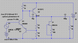
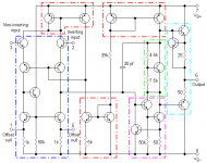
By merging it with the Rush Cascode, I can run it at a gain of 10 at reasonably low distortion into a 1k load.
Implications:
1: I recommend using at least 1-2V bias voltage across the B-C junction of Q3. This bias voltage will be wandering by the same amount as the input voltage, which you may have to adjust for.
2: In order to keep a healthy B-C bias on Q3, you will have to have a supply voltage that is at least the bias voltage multiplied by your gain, plus the Vbe of your output device.
3:To get the low distortion, there has to be a high bias current through the output device.
4: C1 is necessary for stability.
Pros:
1: Higher possible gain.
2: Lower distortion.
Cons:
1: Will require higher voltage supplies for higher gain without making the circuit more complex.
2: Requires decent bias current through the output device to achieve low distortion.
Despite the disadvantages, it still performs better than the CFP gain stage at lower gains where you can use a lower supply voltage. The CFP gain stage is mentioned by Doug Self here:
http://www.dself.dsl.pipex.com/ampins/discrete/twoq.htm
I don't know if this is useful, but maybe it will at least interest you. Personally, my interest in the circuit is in the application found for the Rush Cascode.
Another thing I find interesting is the direct correlation between OP bias current and distortion. It is a perfect example of Class A I guess.
The circuit can probably be modified to phase out the mentioned shortcomings, but I haven't done much simulation in this direction.
So I would say that my biggest question is whether or not this circuit is adequate to be used commercially IE whether or not it is comparable to the other circuits available.
The circuit presented has a gain of 10 and a distortion of .0002% at the present signal levels. Output is 1V pk-pk.
The Jfet current source can be replaced with a resistor with and you will still have reasonable performance.
And yes, I know that I'm abusing that BC557...
- keantoken
As many of you are probably aware, I like screwing with the Rush Cascode.
Doug Self mentions the CFP gain stage on his site, but states that it has troubles reaching a gain of higher than 3 and it is difficult to adapt it to higher output power.
I've solved at least on of these problems.
By merging it with the Rush Cascode, I can run it at a gain of 10 at reasonably low distortion into a 1k load.
Implications:
1: I recommend using at least 1-2V bias voltage across the B-C junction of Q3. This bias voltage will be wandering by the same amount as the input voltage, which you may have to adjust for.
2: In order to keep a healthy B-C bias on Q3, you will have to have a supply voltage that is at least the bias voltage multiplied by your gain, plus the Vbe of your output device.
3:To get the low distortion, there has to be a high bias current through the output device.
4: C1 is necessary for stability.
Pros:
1: Higher possible gain.
2: Lower distortion.
Cons:
1: Will require higher voltage supplies for higher gain without making the circuit more complex.
2: Requires decent bias current through the output device to achieve low distortion.
Despite the disadvantages, it still performs better than the CFP gain stage at lower gains where you can use a lower supply voltage. The CFP gain stage is mentioned by Doug Self here:
http://www.dself.dsl.pipex.com/ampins/discrete/twoq.htm
I don't know if this is useful, but maybe it will at least interest you. Personally, my interest in the circuit is in the application found for the Rush Cascode.
Another thing I find interesting is the direct correlation between OP bias current and distortion. It is a perfect example of Class A I guess.
The circuit can probably be modified to phase out the mentioned shortcomings, but I haven't done much simulation in this direction.
So I would say that my biggest question is whether or not this circuit is adequate to be used commercially IE whether or not it is comparable to the other circuits available.
The circuit presented has a gain of 10 and a distortion of .0002% at the present signal levels. Output is 1V pk-pk.
The Jfet current source can be replaced with a resistor with and you will still have reasonable performance.
And yes, I know that I'm abusing that BC557...
- keantoken
Attachments
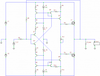
Rush Cascode... nice to learn that it has a proper name, I've only ever known it as a common-emitter common-base cascade, or an asymmetrical LTP. The 741 uses it in its input stage, although biased so it's class A. I have experimented a bit with it a few times over the years, and keep meaning to apply it more seriously (I've attached a schematic of the last attempt). All indications are that it should yield similar performance to a normal LTP, but much faster because it is class AB. It's just that annoying DC offset that causes trouble.
Anyway, I suppose that's off-topic.
Anyway, I suppose that's off-topic.
Attachments
In my experiments on the simulator, I have been able to get outstanding results with the rush cascode, possibly better than the LTP.
Firstly, the rush cascode has less parasitics if you take into account the CCS/resistor used in the conventional LTP. This makes it faster and less prone to oscillation.
Stability can be adjusted via a resistor between the emitters just like degeneration on an LTP.
Distortion is primarily 2nd harmonic, so it should be more pleasant sounding than the LTP.
I have come up with a temperature compensated scheme that fixes the DC offset for the feedback, but the input side is more difficult, because the input resistor causes offset due to base current. I can post if you are interested. But that is probably a subject for another thread.
The simplest and maybe best method is to just use a DC servo.
- keantoken
Kean,
That is absolutely brilliant, haven't seen anything this simple and elegant for some time!! Congratulations!
I've been interested in Rush cascodes and CFPs for about 15 years, and this simple circuit gets around the problem of heavy current variation through all devices and the divider string - it's very clever.
I give you strong credit, this is similar to a gain block I use in a tube hybrid preamp product, but I believe it's superior, and should have very low distortion.
BTW, the RC is extremely amenable to a very small stabilising resistor between the emitters, typically dropping around 0.2V. This degenerates the gain, and improves stability margin.
Well done, wonderful circuit!!
Cheers,
Hugh
Thank you!!!
This is exactly what I was aiming for. I know that most of the good simple circuits are already made, but I have been wanting to discover more of them...
Something tells me that I might later regret putting all my good ideas on this forum, but I don't want to trade present benevolence for future prosperity...
At any rate, I personally would rather put all my good ideas in public domain than risk having patent troubles. Then I can use them whenever I want and have other engineers' input on them. For now I'm interested in intellectual rather than commercial value.
- keantoken
I would be interested if you want to post that one day. I did a temperature compensated version by simply duplicating the entire input stage and using it to buffer the non-inverting input, but the component count increases a lot.keantoken said:...I have come up with a temperature compensated scheme that fixes the DC offset for the feedback, but the input side is more difficult, because the input resistor causes offset due to base current. I can post if you are interested. But that is probably a subject for another thread...
You're one of the very few people I've ever seen make any attempt to use a Rush Cascode in audio. I have pointed out its possibilities a few times before, but no one ever seems interested.
Honestly, I've kind of given up on it too. I've been using LTPs for now.
But now that I'm conceptually comfortable with the LTP, I think I should mess with it again. I posted some designs with it some time ago on this forum.
I did the exact same thing, and it solved the input problem, but I had stability issues because I wanted perfect THD at 20KHz... Plus, it increased distortion beyond .00011%. Horrors!!! (that was me way back when... One year ago :/)
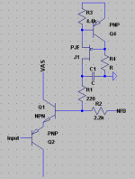
Here is the compensation idea (if there is any interest I will make a new thread). You must choose Q4 to have a tempco as close as possible to the average between the Rush transistors. the 2.2k resistor generates two Vbe voltage drops (think of a Vbe multiplier). Since temperature affects the CCS current, there will be a temperature compensating affect across the 2.2k resistor.
The feedback capacitor will filter all noise injected from the CCS.
Again, the input side is still floating... I don't know how to fix this.
- keantoken
But now that I'm conceptually comfortable with the LTP, I think I should mess with it again. I posted some designs with it some time ago on this forum.
I did a temperature compensated version by simply duplicating the entire input stage and using it to buffer the non-inverting input, but the component count increases a lot.
I did the exact same thing, and it solved the input problem, but I had stability issues because I wanted perfect THD at 20KHz... Plus, it increased distortion beyond .00011%. Horrors!!! (that was me way back when... One year ago :/)
Here is the compensation idea (if there is any interest I will make a new thread). You must choose Q4 to have a tempco as close as possible to the average between the Rush transistors. the 2.2k resistor generates two Vbe voltage drops (think of a Vbe multiplier). Since temperature affects the CCS current, there will be a temperature compensating affect across the 2.2k resistor.
The feedback capacitor will filter all noise injected from the CCS.
Again, the input side is still floating... I don't know how to fix this.
- keantoken
Attachments
Thank you, I have been referred to it (by you I think) but didn't find it.
Update.
I just grafted the Rush very quickly onto my class A amplifier, and it has what I think is a good effect. No stability problems since I use a proper Cdom.
http://www.diyaudio.com/forums/showthread.php?postid=1862357#post1862357
If I get my prototype working, I'll have to try this.
- keantoken
AKSA said:Kean,
Take a look at the master, the NAD3020 phono stage from Tomlinson Holman, of THX fame. This was done on commission as he was completing his PhD about thirty years ago!!
Hugh
Hello Hugh
The first NAD3020 amp, phono stage, was considered as one of the best phono stage on the market and some guys was using it with high-end power amps.
Thank for posting it, I did have only the NAD3020B conventional phono stage version schematic only, maby I should do that Tomlinson Holman version as phono preamp, maby it could be better than using a OPA637 op amp for a phono preamp.
But the NAD3020B amp was no more using this phono stage and did use a more conventional version phono stage, I include the NAD3020B phono stage schematic.
Thank
Bye
Gaetan
Attachments
It's a common error to think that a circuit with a common base transistor can be called a cascode circuit. The Rush circuit is not.
It's a circuit with coupled emitters just like an LTP, it is a series differential stage, an LTP being a parallel one. Compared to an LTP, it may be nice in some applications because of less parastic capacitance, but as both transistors share the same current, its gm has poor linearity. This is a fact known since a very long time and explained why the Rush circuit is so rarely used. There is one used as an intermediate stage in Cherry's NDFL amplifier.
It's a circuit with coupled emitters just like an LTP, it is a series differential stage, an LTP being a parallel one. Compared to an LTP, it may be nice in some applications because of less parastic capacitance, but as both transistors share the same current, its gm has poor linearity. This is a fact known since a very long time and explained why the Rush circuit is so rarely used. There is one used as an intermediate stage in Cherry's NDFL amplifier.
Sebastien,
It has high gain, is blisteringly fast, and simulates well in the circuit supplied by our clever young Texan Keantoken.
I make 1.4 degrees of phase shift at 100KHz, not too shabby, a noise floor at -97dB (more in some simulations), a fb factor around 37dB with 33R of inter-emitter degen, and H5 at -119dB in a CLG circuit at 30dB. All this with minimal lag compensation, too!
It may be terrible in theory, but heck, man, it sims well, enough to show promise in breadboarding.....
Ciao,
Hugh
I'll have to finish what I started now. I did a whole slew of permutations of the circuit I posted, and was going to write an article on it, but I became distracted by other projects. I built a few on the breadboard and they seemed to work pretty well.keantoken said:Honestly, I've kind of given up on it too. I've been using LTPs for now.
But now that I'm conceptually comfortable with the LTP, I think I should mess with it again. I posted some designs with it some time ago on this forum...
Interesting. It's the opposite to the way I was trying to do it (variable current source instead of variable voltage source). The large input bias current though... It may be alright if the output stage has a very high quiescent current so the bias current is relatively small, but it would not be so good for general use.keantoken said:...Here is the compensation idea (if there is any interest I will make a new thread)...
I'm sure everyone is already familiar with this, but attached is a schematic of the ancient 741, showing how it deals with it - DC offset cancelled by using two pairs, and floating bias.
Attachments
forr said:It's a common error to think that a circuit with a common base transistor can be called a cascode circuit. The Rush circuit is not.
It's a circuit with coupled emitters just like an LTP, it is a series differential stage, an LTP being a parallel one. Compared to an LTP, it may be nice in some applications because of less parastic capacitance, but as both transistors share the same current, its gm has poor linearity. This is a fact known since a very long time and explained why the Rush circuit is so rarely used. There is one used as an intermediate stage in Cherry's NDFL amplifier.
I have been considering whether I should call it the Rush Cascode or not for this reason. I think that name is misleading, everyone thinks that one input will be held at constant voltage. Not to discredit Rush, of course.
- keantoken
I think it should be called a "no tail pair".keantoken said:
I have been considering whether I should call it the Rush Cascode or not for this reason. I think that name is misleading, everyone thinks that one input will be held at constant voltage. Not to discredit Rush, of course.
- keantoken
Mr Evil said:
I think it should be called a "no tail pair".
NTP. Good call. So it's easy to see the differences between an LTP and NTP...
4QDtec calls it the "complimentary long-tailed pair". CLTP.
I think the tails are still long though.
- keantoken
Hi,
Done a quick simulation of two unity gain followers
- CFP loaded by a 6 mA CCS
- Rush pair input + EC load by a 6 mA CCS, 100% NFB
bipolars 2N2222 and 2N2905
+/- 20 V power supply
both loaded by a 2.8 kOhm connected to ground
input signal 10V
The CFP has about half the distorsion of the Rush+EC follower
0.002 % vs 0.004 % input collector load 2.2 kOhm
0.003 % vs 0.006 % input collector load 4.7 kOhm
Using an LTP with a 0.6 mA CCS for the input and 2.2 kOhm collector load gave slightly worse results than the CFP. With a current mirror, it was almost halved ar 0.00125%.
For 1 V input, in every case, the distorsion is extremly low.
Only simulations using TINA....
- Status
- This old topic is closed. If you want to reopen this topic, contact a moderator using the "Report Post" button.
- Home
- Amplifiers
- Solid State
- CFP gain stage, modifications.