I've noticed that many amps use a DC servo FB loop to control DC offset at the output. Some of these circuits are fast acting op amps. What prevents them from trying to adjust out low frequency audio? Is it just a simple matter of setting them to only react below 20hz?
Thanks all.
Thanks all.
Is it just a simple matter of setting them to only react below 20hz?
Yes. The usual arrangement is an inverting integrator (i.e. 1st-order low-pass filter) stage, with the cutoff frequency well below 20Hz to avoid any audible phase shifts or bass loss. This basically takes the DC content of the output, inverts it, and feeds it back into the circuit. Over time this correction signal will converge so that the output DC voltage is 0. The transient characteristic is the typical first-order exponential settling.
Paranoid designers might add passive low-pass filters to the input and/or output of the servo, in case there are high-frequency issues (positive feedback) with the feedback loop. One of my circuits required T networks on the input and output for stability, due to the insane bandwidth of the amplifier in the servo loop.
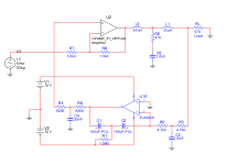
Here's what I did for my headphone amplifier. The virtual opamp on top is the discrete opamp I designed - bandwidth is 35MHz, slews 1000V/uS.
The cutoff frequencies of the two T networks are not terribly critical. What's important is that the impedance is in the right range, so that kind of determines the resistor values. The cutoffs can be in the audio band; the audio signal through the servo in the KHz range is insignificant so it does not matter. I used some good high-frequency film caps I had on hand.
The 1M resistor provides bias voltage for the electrolytic integrator caps, to promote oxide self-healing. Since the caps have leakage current, this adds some offset voltage too, but it's pretty low. The resistor could be made 4.7M if there is too much offset.
Attachments

Hi
You can look at it as creating a dynamic virtual gnd reference for the input stage, which is in respect to the output DC. In one of my circuits, it is a balanced amplifier with two inputs so there are two discrete servos (just a couple of simple LTP's and VAS’s), with Fc ~3Hz. They create the virtual ground references needed for common mode stability and maintaining 0V at each output.")
You can look at it as creating a dynamic virtual gnd reference for the input stage, which is in respect to the output DC. In one of my circuits, it is a balanced amplifier with two inputs so there are two discrete servos (just a couple of simple LTP's and VAS’s), with Fc ~3Hz. They create the virtual ground references needed for common mode stability and maintaining 0V at each output.
- Status
- This old topic is closed. If you want to reopen this topic, contact a moderator using the "Report Post" button.