Hello every one, I would consider this my second major solid state amplifier project, but with this one it will be like rebuilding an entirely new amplifier, so I am making an attempt to make the best one I can from what I've salvaged from this one and whatever else I can find in my junk piles.
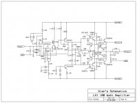
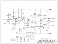
The amplifier is made by Sears (go figures, considering there is no info what so ever about it). It produces 100 watts into 8 ohms and consider how cheaply made it is, it sounds really good and is a well designed amplifier. I even took the time out to draw up a schematic, which can be used for the convenience and personal use of others.
I have many ideas in mind of how to modify the circuit for improvements, but only understand the basics, so I am looking for ideas of what would make this circuit better, more current capable and efficient.
I have made a few posts on the Class "A" Hybrid Amplifier thread but have not had much help there since this is a class "AB" amplifier, that I indeed want to turn into a Hybrid of some sort, mainly to get rid of the obsolete chip fet at the input stage of the amplifier, so I am more than willing to be walked through the modifying process, as I now have all SUMMER!!!
Here is the original schematic that I drew up, if there are any reasons why what I drew up may not work please let me know! I will correct it as necessary.
Attachments
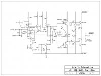
Now here is what I have come up with so far, removed the output short circuit protection (but will most likely make a seperate board for it as an addition). And also removed the output inductor (I hope this doesn't affect performance in any way, but this is how the ESP P3A is). Increased Emitter resistors from 0.27 ohms to 0.33 ohms (An attempt to lower distortion, but will reduce output power some what, not a problem for me). Lastly I thought that decreasing the 220pF caps on the drivers might make for some improvement (Also a point read on the P3A cercuit).
Other than that it looks the same, but with paralleled Less obsolete Toshiba's. And some components I don't really understand thier purpose, like the 3.3 ohm resistors on the bases of the outputs (changed them to 10 ohms like on the Leach Amp) or the 270 ohm resistor and 0.1uF capacitor between the driver transistors. And the two diodes that look like ordenary 4148's, if some one could identify them that would be nice (If you can understand the circuit in the first place. )
So here is the new schematic...
Other than that it looks the same, but with paralleled Less obsolete Toshiba's. And some components I don't really understand thier purpose, like the 3.3 ohm resistors on the bases of the outputs (changed them to 10 ohms like on the Leach Amp) or the 270 ohm resistor and 0.1uF capacitor between the driver transistors. And the two diodes that look like ordenary 4148's, if some one could identify them that would be nice (If you can understand the circuit in the first place.
)So here is the new schematic...
Attachments
CrazzyAbtTubes said:Soooo, exactly what would be the purpose of these diodes? Do I need them, is there anything gained from removing them?
If your not using the short circuit protect then the diodes are not required.
The diodes stop the transistors reverse biasing.
Thanks for the info, like I said I will probably lay the board out so that I can have the short circuit protection optional, just in case the amplifier is used on harsh loads some time in the future.
Now I just have to figure out the input stage, I can't find a data sheet for the UPA63H so I can find substitutes, unless like I said, the input stage could be some how subed with a tube but would require much chang in circuit design.
Now I just have to figure out the input stage, I can't find a data sheet for the UPA63H so I can find substitutes, unless like I said, the input stage could be some how subed with a tube but would require much chang in circuit design.
i have been
priviliged to repair one of these amps ...made in korea for sears and actually left me totaly breathless with the performance
your approach though is wrong from two points
A) it seems to me that you dont have enough skills to do a thing like that
B) it also seems to me that you havent really evaluated what you allready have in your hands
you need first to decide what you like to do
A) built a new amp based on this schematic ( pcb layout and everything else )
B) repair and/or upgrade the existing one
if you go for section B then there is a few things that it can be done
basicly what i do is very wrong cause it seems that you dont know much about amps and this will bring endless emalis and a very long post that will only end up in smoke
what you describe as ''''''obsolete chip fet at the input stage of the amplifier''''''' is what make this amp unic and amazing performance without any improvemnts Imagine what is going to happen if you start tweaking things arround
i know some people that will kill somebody just to lay hands on chip fets like that
please dont missunderstand me i am not willing to make a personal attack to you ( i dont even know you ) but i think is better to listen from some one the "hard " way and save one amp from smoke
since i am familiar with the particular amp i will be very happy to help you taken as a fact that we speak the same "language"
happy regards
now that i read more
carefully
...... god you cannot use advices from the P3a threads or esp pages !!!!! P3a isa bootstrap CFP ..... your is a ccs EFP ..... does all this sound chinese to you ?????
these amps are totaly diferent ...you cannot copy tips and fragments from one to each other ....
to nigelwright7557 :
you seriously need to clarify better which diodes you are talking about ....you are probably talking about the diodes that are part of the VI limiter but why i have a strange feeling that our friend is talking about the string of diodes that are located in the lower area and are part of a ccs ?????
here i will use one of the best Andrew T said
should i duck now or wait for the smoke first ????
Re: i have been
I don't think my LXI is the same -- dual mono DC MOSFET -- but it is a surprising good sleeper amplifier. Pretty sure it was built by Hitachi. The accompanying Pre-amp is not bad either. One of the things that makes the amp/pre/tuner special is that my net cost was -$400
Like some of the Radio Shack stuff, some of these house brand items, built by solid OEMs, can be real sleepers. (Another Sears house brand, is their professional speaker, which provides 2 quite good Foster 28mm silk dome tweeters, and a 12" Foster midbass per speaker -- the same woofer & domw + a really nice Foster inverted 1" dome can be found in an AGS branded speaker).
I did think it was 100W but Daniel measured it at 150W and solid into 4 ohms. He srtipped out some wiring & switches, installed a gain pot, and increased the bias so that it stays in Class A till 10W. I use it as a woofer amp (mostly to drive push-push SDX7).
dave
sakis said:priviliged to repair one of these amps ...made in korea for sears and actually left me totaly breathless with the performance
I don't think my LXI is the same -- dual mono DC MOSFET -- but it is a surprising good sleeper amplifier. Pretty sure it was built by Hitachi. The accompanying Pre-amp is not bad either. One of the things that makes the amp/pre/tuner special is that my net cost was -$400
Like some of the Radio Shack stuff, some of these house brand items, built by solid OEMs, can be real sleepers. (Another Sears house brand, is their professional speaker, which provides 2 quite good Foster 28mm silk dome tweeters, and a 12" Foster midbass per speaker -- the same woofer & domw + a really nice Foster inverted 1" dome can be found in an AGS branded speaker).
I did think it was 100W but Daniel measured it at 150W and solid into 4 ohms. He srtipped out some wiring & switches, installed a gain pot, and increased the bias so that it stays in Class A till 10W. I use it as a woofer amp (mostly to drive push-push SDX7).
dave
Re: now that i read more
Whoops ! apologies.......
I didnt see the diodes in the CCS, I just assumed he was talking about the diodes in the short circuit protect cct.
sakis said:carefully
to nigelwright7557 :
you seriously need to clarify better which diodes you are talking about ....you are probably talking about the diodes that are part of the VI limiter but why i have a strange feeling that our friend is talking about the string of diodes that are located in the lower area and are part of a ccs ?????
here i will use one of the best Andrew T said
should i duck now or wait for the smoke first ????
Whoops ! apologies.......
I didnt see the diodes in the CCS, I just assumed he was talking about the diodes in the short circuit protect cct.
Thank you very much, I am glad to finally come across someone who can make sense of this circuit, sakis.
I can still be considered a beginner in the solid state theory because I usually work with tube related stuff, but I have multiple amplifiers I have been working on over time, this being one of them, and actually works just fine except the input switch.
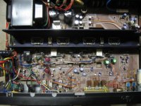
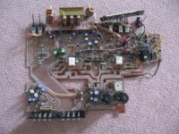
I also have pictures on another forum if you are interested to see what I actually have.
Thank you for saying that, it is not offensive to me at all because it really is true.
Yes thanks, allot, I was pretty sure those two diodes were needed, but the amp really would have gone up in smoke because I removed them from version 2 of the schematic.
Now, from what sakis said I should just stick with the original schematic (good idea in my terms). As for the fet at the input stage, I was hoping that I could use individual fets, but that would require hours of matching that I really wouldn't look forward too.
And don't worry I have like five copies of the original schematic on my computer and hav'nt removed a part from the main board, but would like to make seperate boards for the amplifier itself, most likely by drawing it up in express PCB then making a point-to-point set up (I have no experience with making PCB's and don't have the money to have them manufactured).
Here is the link to the other thread on the other forum with pics of the amp, just so I don't have to scale them down again...
http://diyaudioprojects.com/Forum/viewtopic.php?f=10&t=871
Thank you sakis...
I can still be considered a beginner in the solid state theory because I usually work with tube related stuff, but I have multiple amplifiers I have been working on over time, this being one of them, and actually works just fine except the input switch.
I also have pictures on another forum if you are interested to see what I actually have.
it seems to me that you dont have enough skills to do a thing like that
Thank you for saying that, it is not offensive to me at all because it really is true.
Whoops ! apologies.......
I didnt see the diodes in the CCS, I just assumed he was talking about the diodes in the short circuit protect cct.
Yes thanks, allot, I was pretty sure those two diodes were needed, but the amp really would have gone up in smoke because I removed them from version 2 of the schematic.
Now, from what sakis said I should just stick with the original schematic (good idea in my terms). As for the fet at the input stage, I was hoping that I could use individual fets, but that would require hours of matching that I really wouldn't look forward too.
And don't worry I have like five copies of the original schematic on my computer and hav'nt removed a part from the main board, but would like to make seperate boards for the amplifier itself, most likely by drawing it up in express PCB then making a point-to-point set up (I have no experience with making PCB's and don't have the money to have them manufactured).
Here is the link to the other thread on the other forum with pics of the amp, just so I don't have to scale them down again...
http://diyaudioprojects.com/Forum/viewtopic.php?f=10&t=871
Thank you sakis...
this is all pointless
since you need to login or register to see the pictures
beyond that .... and since we made some things clear i would be very happy to tell you the mods and tweaks i ve made to the sears amplifier and see if you can gain something out of this ...
keep me posted
since you need to login or register to see the pictures
beyond that .... and since we made some things clear i would be very happy to tell you the mods and tweaks i ve made to the sears amplifier and see if you can gain something out of this ...
keep me posted
ok
here is the list of mods
----recap the all unit
----change the capacitor in the input of the amplifier to something a lot better than it used to be ( option to bypass it also with 100nf is good ) ]
----replace psu caps with the bigest available to fit in this area
---- add ggod quality by pass 100nf down under of the above
---- totally remove speakers AB switch
---- use twisted pair 1.5mm directly from amplifier boards to out
---- replace all resistors that are related to LTP +VAS + ccs Stage with metalfilm 1% prefered
---- replace all ceramics with better (styroflex ,multileyer or mica )
the capacitors that are critical to replace is the capacitor that formates the input filter , then the capacitor between B+C on the VAS amplifier , then the capacitors located in the same pins in the drivers area .....
there are a couple of options about that ..... others use arround 100 pf in the VAs area and then leave frivers free ....or with small caps ....or the other way arround ...use very low in the vas area like 10-20 pf and then "guard" the drivers with 100-220 pf
your aim about these caps is to low them as much is possible but carefully since oscilation is waiting arround the corner ( also this is load depending )
----all the above will require scope and gen
---- finally you may relocate zobel on the binding post since speakers AB switch is removed and if you do that a seperated trace to ground is a must
---- you may also like to beef up idle ( before that you need to have all your "mechano" done: new thermo transfer paste plenty and fresh applyied to all transitors on the heatsinks tight all related screws and make very very sure that small transistor Vbe multiplyer is firmlly attached on the heatsink to monitor amplifier temperature )
beefing up the idle will increase the quality of the amp but will also thermaly stress the amplifier the balance between those two is your choise as the same is casual listening or full power listening (beefing up the idle will alter the safety margin of the amp at full power ) you may be carefull about this
another thing i do but this i will say it as an option since a lot of people may have another opinion ...... in this amplifier the case is also psu ground ..... well i like to seperate this so i use a grounded ps cable with three pins ...provide ground to the box from the mains and keep the psu ground totaly diferential
i dont thing that there is anything else that it can be done to this amplifier ....allready all the above mentioned is too much but since the cost is very low WHY NOT ?????
I did forget to mention to you that I do have a scope, but it is really old, but still does it's job and although I have not much experience with them I understand the basic functions. As for the signal generator... it is a full tube unit that is moderately reliable but could use a bit of upgrading, cleaning, and maybe some metal film resistors would make it better and more reliable, don't really know but both were donated to me by a fellow ham. Now what I really need is a square sine signal generator, and some way of measuring distortion....
Allot of the mods you mentioned I had all ready pre-planned, but really the only one I need help on is the paralleling and substitution of the output transistors, that is if this mod is even possible on this design.
If not than I definetly have to leave the short circuit protection circuitry in and hope to god that I never blow up the output stage for some careless reason.
I also need to know if the amplifier will handle higher voltage rales, say 50V, I think it would bit have know idea what effects this will give in terms of power output and such. Reason why I am asking is just in case the toroid tranny I salvaged from another has a voltage higher than that of the original IE core tranny in this amplifier, which is 33-0-33VAC.
noap !!!!!
50 volt rails is by far more than the amp will handle ....you will exceed the soa of the amplifier ...then the VI limmiter that you removed will need to be installed again and modified to operate at this voltage
i will say NO to this
you may proceed with all the rest
scope doesnt need to be realy that acurate .... genarator also just a couple of things you need to see
you may
also find procedure and more info here .....take a look it might be handy vintage amplifier repair/upgrade manual
also find procedure and more info here .....take a look it might be handy vintage amplifier repair/upgrade manual
Schematic update!
I have an updated schematic! DO NOT USE THE OTHERS this is version 2.5 and the reason being that most of the PNP's are not oriented right (emitters and collectors are shown wrong).
This is the last schematic until this project is done, and may be a while, because I have other equipment and projects that need finnishing.
Attachments
Prototype?
It has been a long time since I have looked at this project, but in that time I have been gathering parts and just today I threw my version of the circuit onto some clad board and amazingly the amplifier powers up from a 12V+/- supply no problem and it even produces audio... well... almost. I am using 32 ohm headphones to test the amplifier my ipod and a small tube preamp.
The amplifier seems to clip really badly even at the lowest level, although is not as bad at lower levels as higher levels. Does anyone know what this could be caused by? I am thinking that because the voltage supply is so low, that the input LTP FET does not have enough supply voltage getting to it because it sounds nothing like an oscillating distortion.
If I do get this amplifier working in the mean time I will have to take a picture of it.... I looks like a bunch of junk using recycled 10% carbon comp resistors and a pair of beefy 150 watt Sanken outputs!!
- Home
- Amplifiers
- Solid State
- Modifying 100 watt LXI amplifier circuit