Member
Joined 2009
Paid Member
The TGM2 project is going well, but too many ideas to incorporate into my HT project and I don't want to lose sight of them [http://www.diyaudio.com/forums/showthread.php?s=&threadid=145652]. So time to start a new thread for a new amp. This will be a Stereo amplifier; not sure if and when it will be built though.
I promised Carlos that I would rise to the challenge of trying something a little different.
Two things I will do differently, 1) make this a guitar amplifier for hi-fi, 2) explore an old output topology that I haven't seen much of before which was invented by Blomley.
Why guitar ? - these guys are experimenters, they have fun with their amplifiers. I like that. They like distortions. Me too. They want a high quality amp that performs cleanly when asked for. So we need an amp with a baseline of low distortion.
A common and widely published method to get some guitar amp sounds is the simple diode soft-cippling circuit. I tried this in my sims, but it didn't quite work as I wanted. Another method often touted is based on a JFET which has a characteristic that varies from square law to exponential depending on how it's used. With this you can really create havoc with an amplifier.
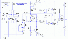
So first up is the JFET option. I needed somewhere in the amplifier signal path that has relatively low voltages and currents. So I chose the shunt part of the feedback loop and popped in my JFET. Schematic is attached (Wavebourn has probably seen this before). It's a 'Triode' in the feedback loop. It's just a starting point, it needs to be refined and I want it adjustable.
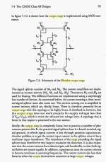
Why Blomley, well TGM2 allowed me to explore improvements to the front end of the amplifier so next up is the driver stage. The Blomley is a non-switching ClassAB topology that offers some benefits. I know nothing much about it so it will be an interesting learning opportunity which is what this is partly about.
I haven't decided on a name yet, I chose 'Harry 77' in honour of Harry Joyce [http://www.harry-joyce.com/hjspecs.htm] who during his time hand-built to military spec. some fine guitar amplifiers; I fancy something that can deliver around 77W peak power.
Attachments
Member
Joined 2009
Paid Member
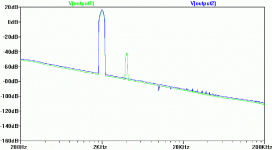
And here's the FFT showing the baseline (blue trace) without the 'triode' in the feedback loop compared with the schematic that does include the JFET (green). Lots of H2. Some other related topologies give some H3 so maybe we can optimize this.
Of course, unfortunately, I don't have an electric guitar to try it out with.
Of course, unfortunately, I don't have an electric guitar to try it out with.
Attachments
Member
Joined 2009
Paid Member
Member
Joined 2009
Paid Member
and I'm trying to understand how it is that common emitter and common collector can be the same thing when you move from PNP to NPN.
Well, I've done a lot of reading about non-switching outputs. There is a huge mountain of knowledge out there, it's simply scary. I've hardly scratched the surface.
The Blomley might have been my starting point but I'm starting to doubt that it will be the end point. First off, I have yet to get a sim of the Blomley output working properly.
I have seen so many designs (like current feedback amplifiers that look like the Blomley, like simple diode+resistor non-switching techniques and now I am really admiring the Steven Dunlap deisgns)... my head is spinning.
I re-read the Frugal amp thread (around page 30) and yet more information pouring in.
then I find this link:
http://www.tubecad.com/2006/12/blog0091.htm
Interesting reference to a patent by Brent Butler. It uses tube pre-distortion to linearize a transistor. But this concept is an old idea, I've seen it before, patented in solid-state implementation by Gilbert for use in LTPs. Even the experts are going in circles, what hope for me ?

Bigun said:And here's the FFT showing the baseline (blue trace) without the 'triode' in the feedback loop compared with the schematic that does include the JFET (green). Lots of H2. Some other related topologies give some H3 so maybe we can optimize this.
Of course, unfortunately, I don't have an electric guitar to try it out with.
This looks high enough that you can run a .wav file through it in the circuit and possibly "hear" what the circuit will sound like. If you use LTSpice you can do this (if I remember right you run LTSpice on a mac through a special program?)
The help file tells you how to do it in LTSpice.
- keantoken
Member
Joined 2009
Paid Member
I didn't know you could put a sound file through it, that would be very interesting. I still don't have the software on my Mac though, you have to buy not only a virtual machine emulator but also you have to buy Windows. I will think about it.
I promised Uncle Charlie to try and give more thoughts to how my distortion generation is working. So I will start here.
But this is only a start, I will be looking at other ideas too.
why am I using an active device in the feedback loop and how does it work ?
First off, we want to add/control the flavour of harmonic distortion in the output of the amplifier. (We are ignoring the argument against flavoured amplifiers, this thread is only for people who like some spice). Some people are able to finesse their amplifier designs to achieve a certain harmonic profile and other wonderful sonic attributes. Grand Masters like Nelson Pass, Hugh Dean etc. are able to do this to a high degree of fidelity. The rest of us (OK, me) are looking for something within our more modest capabilities, so we look for the brute-force approach. We start with a good basic clean amplifier and then generate distortions. This means we need a non-linear device.
2nd Harmonic:
Many people say they prefer the flavour from tubes, especially from triodes. Triodes work only with electrons and differ from most transistors by having non-exponential behaviour. In particular their transfer curves generate a lot of 2nd order harmonics (H2). This seems mostly to be true with low powered SE triodes, at higher powers and with Pentodes the higher order harmonics are more visible. See measured haromonic data at: [http://greygum.net/sbench/sbench/testamp.html] "The results were very interesting. Almost everyone preferred the higher distortion but only second order distortion for all musical selections except for "rock"."
Notice some key things from these measurements. First off, H2 dominates. But a more subtle and interesting feature is how harmonics scale with amplfier output power. Generally H2 starts out high and stays high at a fairly constant % of the signal. The higher order harmonics are much lower but increase with power until their levels are not so different and are comparable with H2. So we want to be able to generate H2 at a consistent level.
Generating clean H2 rules out devices with exponential transfer curves like BJTs and Diodes.
A Triode generates H2 with it's quadratic-like transfer curve. A JFET approximates this behaviour for small signals (a BJT does not).[http://freespace.virgin.net/ljmayes.mal/comp/vcr.htm] but we don't want to do that.
The first version of Harry77 puts the JFET into the required small-signal 'triode' region by dropping the feedback shunt signal voltage across a series resistor.
In general, the JFET gate bias should always be negative but as long as we avoid fwd biassing the diode that forms the gate junction we can let it swing + and - with the signal. For now I've used a simple approach with the gate pinned to signal gnd and works because the dc-offset of the output is reasonably low. At some point we will arrange it so that the amplifier clips before it's able to fwd bias this base junction.
I've put a bypass resistor across the drain-source to create a pair of parallel resistors, one the non-linear JFET, the other a regular linear resistor. By chaning the value of the bypass resistor we can control the amount of non-linearity and so we have a 'knob' to control the amount of H2. It has a parasitic impact on overall gain however.
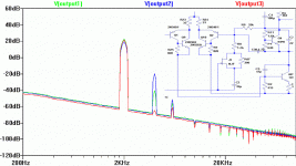
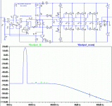
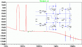
Attached shows FFT (with circuit inset) where the JFET bypass resistor has been changed. Red = no JFET, Green = 390R, Blue = 1.8k. It's the same story at 20kHz as at 2kHz.
Attachments
Some also say that 3rd harmonic is desirable at low frequencies. By adding a few more components and another nonlinear device, maybe you can do this. Perhaps you can add another FET in the opposite polarity as the first one, that becomes active at LF and cancels the even harmonics, leaving 3rd harmonics behind.
- keantoken
- keantoken
Member
Joined 2009
Paid Member
Yes, I think we can do this to generate H3. I saw something with diodes in my sims that produced some H3. The output stage tends to turn H2 into H3, we may only need to make H2 and we get some H3 for free ?
I need to start looking at the output stage. Something interesting should come out of looking at the designs by Wavebourn, Steven Dunlap and Blomley.
Some kind of non-switching design with Steven Dunlap drivers and a CFP output with soft-clipping.
I need to start looking at the output stage. Something interesting should come out of looking at the designs by Wavebourn, Steven Dunlap and Blomley.
Some kind of non-switching design with Steven Dunlap drivers and a CFP output with soft-clipping.
Member
Joined 2009
Paid Member
reducing higher order odd-harmonics
First thing was to see the benefits of more output devices. For higher power people use more devices, but I am also interested in the impact on FFT.
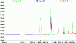
So I increased Harry rails to +/-36V (was previously at +/- 26V inherited from TGM2) and looked at 3 options, single, double and triple output pairs.
I looked at driving a 20kHz sine wave of +/-22V into 8Ohm + 10nF load.
Topology is still basically TGM2.
Additional output pairs cleans up H2, but most importantly it reduces higher order odd-harmonics. This is very desirable.
Attached shows outputs labelled with the qty of output pairs used (5200 type devices)
Attachments
Member
Joined 2009
Paid Member
non-switching output
I have been unable to get the Blomley working in the sim yet, so I took a diversion to a simpler scheme invented by Technics. This will help me learn and understand more about this so-called non-switching AB output.
What I like is that it requires few components and can be added to the existing EF output stage without changing the topology – so it’s easy to remove again. See:
http://www.diyaudio.com/forums/showthread.php?threadid=922
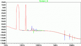
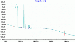
First results are attached. What you see is the simple diodes added to Harry77 output. The FFT plot shows the Harry77 without the diodes (green) and with the diodes (blue). There appears to be a nice clean-up of harmonics other than H3 (which may in fact be produced in some other part of the amplifier).
(Note that the 2nd harmonic generating JFET in the fdbk loop has been temporarily disconnected)
More comments soon…
Attachments
Member
Joined 2009
Paid Member
How do we know it is non-swtiching ?
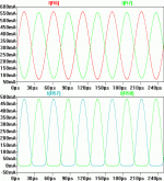
I looked at the current flow through the output device emitter resistors.
The attached shows the story. The lower plot shows the current through the output devices drops to zero and cuts off. The cross-over current is around 50mA, which is where the bias was set up. The upper plot shows the current from the non-switching output, where the devices do not cut-off but stay always conducting.
All is not roses. The non-switching output starts to clip and get nasty before we get anywhere near the supply rails. Some further work is needed to refine this.
Attachments
Member
Joined 2009
Paid Member
Member
Joined 2009
Paid Member
Here's the data over a wider frequency range.
The benefits disappear at low frequencies - i.e. the existing Harry77 EF output works just perfectly.
The biassing is still off, it only works up to half the potential voltage swing but at least shows the potential. It's a bit crude.
As before blue line = non-switching, green = regular output
The benefits disappear at low frequencies - i.e. the existing Harry77 EF output works just perfectly.
The biassing is still off, it only works up to half the potential voltage swing but at least shows the potential. It's a bit crude.
As before blue line = non-switching, green = regular output
Attachments
Member
Joined 2009
Paid Member
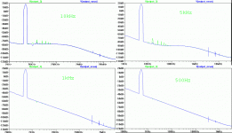
Intermodulation & Temperature
Next up is to see how temperature affects the output and check on levels of intermodulation. Turns out I can't get a sensible FFT if I try putting two signals with closely separated frequencies - does anybody know how to do this ?
I ended up using 5kHz and 15kHz.
I stepped the temperature from 10C to 30C to 90C.
Attached - we see no real problems with IM products but the higher order harmonics swing around with temperature, as expected.
Attachments
Member
Joined 2009
Paid Member
With the non-switching output based on diodes we worry about temperature drift.
Here's how things look at the same 3 temperatures. It doesn't look very pretty, there are several higher order harmonics popping up so we lose the benefits of the non-switching output.
Here's how things look at the same 3 temperatures. It doesn't look very pretty, there are several higher order harmonics popping up so we lose the benefits of the non-switching output.
Attachments
Member
Joined 2009
Paid Member
MJL21193 said:Hi Gareth,
Why do you have the fundamental for the FFT at 20K? All of the harmonics will be outside our range of hearing.

Usually, the FFT at 20KHz will be the same as at 1KHz, but the distortion harmonics will simply be larger. So it might be useful if you wanted to get past the noise floor. It's no the same with all amps, though.
Just to point it out,
- keantoken
Member
Joined 2009
Paid Member
- Status
- This old topic is closed. If you want to reopen this topic, contact a moderator using the "Report Post" button.
- Home
- Amplifiers
- Solid State
- new amp... HARRY 77
