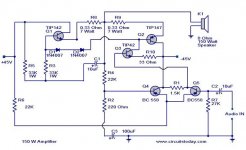
Hi, I found this circuit diagram on internet and I'm interested to make myself one, so I try to make one. First, I have found a version of this diagram using TIP41 as driver transistor. This version is working, just come out a lot of noise and the signal is abnormal when test with oscilloscope. A few days ago, I found another version (90% similar) diagram (pls see the attachment), this version is using TIP 42 as driver transistor. But when my current board change to use the TIP42 transistor, the power amp no longer working and just produce humming sound, I suspect something is wrong with the latest or the second circuit diagram, can anyone help me the rectify it? Thank you.
Attachments

teemuk said:This one again?
Isn't production of TIP142/TIP147 even discontinued now?
is it both tip142 and 147 discontinued already? I still can find it in my country, but don't know any countries still available or not.
The original amp used a TIP41(NPN) as Q3. The schematic you posted shows a TIP42(PNP) but the symbol is still an NPN. An NPN is usually used in that location, so I'm thinking the TIP42 is wrong. Probably why the amp doesn't work at all now. The schematic shown sure is drawn weird. I redrew it the way most amplifier schematics are drawn and it sure makes it easier to digest. As to the sound or well this amp works I have no idea, just commenting on Q3 and the schematic.
Craig
Craig
llwhtt said:The original amp used a TIP41(NPN) as Q3. The schematic you posted shows a TIP42(PNP) but the symbol is still an NPN. An NPN is usually used in that location, so I'm thinking the TIP42 is wrong. Probably why the amp doesn't work at all now. The schematic shown sure is drawn weird. I redrew it the way most amplifier schematics are drawn and it sure makes it easier to digest. As to the sound or well this amp works I have no idea, just commenting on Q3 and the schematic.
Craig
Yeah, you are right, just now I also found that the Q3 isn't right, so changed to TIP41, it works. But the signal is abnormal when test with ocilloscope. Don't know what's wrong with it.
you may
wana take a look at this
it can describe the darligton problems and why amplifiers working with them can fail very easilly if http://www.diyaudio.com/forums/showthread.php?s=&threadid=141780&highlight=not designed properly
wana take a look at this
it can describe the darligton problems and why amplifiers working with them can fail very easilly if http://www.diyaudio.com/forums/showthread.php?s=&threadid=141780&highlight=not designed properly
Matthewong said:
Yeah, you are right, just now I also found that the Q3 isn't right, so changed to TIP41, it works. But the signal is abnormal when test with ocilloscope. Don't know what's wrong with it.
Does it sound bad too, or does the waveform just look all funky? Is anything getting hot?
Could be crossover distortion, oscillating, or the BC558 pair severely out of balance.
This was originally designed (thrown together) as a guitar amplifier so don't expect Hi-Fi.
Original site http://members.fortunecity.com/jtfish/amp/ca100.htm
Tony.
Original site http://members.fortunecity.com/jtfish/amp/ca100.htm
Tony.
Here is one from an old elektor with TIP142/147.
I have several pairs of those old trannies myself and I have been considering making amps with them. Maybe this one would be interesting...
Take a close look, it's rather unconventional.")
An old current dumper variant, published by Elektor in one of their summer editions 30..35 years ago!
An old current dumper variant, published by Elektor in one of their summer editions 30..35 years ago!
Yep, that's the one. It wasn't a full article and that circuit, although it likely works as is, wasn't a full fledged amp.
I could use some improvements and perhaps raise rails a bit to get some more out of it. But it's a cheap build, with rather few and inexpensive parts.
one of their summer editions
Juli/August 1979 edition.
(just think, that same year Elektor did a low power concept of the Technics SE-A1 class A+ power amp. Still a good magazine to read)
- Status
- This old topic is closed. If you want to reopen this topic, contact a moderator using the "Report Post" button.
- Home
- Amplifiers
- Solid State
- Darlington TIP142 & 147 power amplifier.