Member
Joined 2009
Paid Member
I want to continue my learning about amplifiers, started with the TGM1 [http://www.diyaudio.com/forums/showthread.php?s=&threadid=140461], by designing and building a new design, the TGM2.
I'm going to step back and start with just one change to the LTP at first, which is to introduce the complimentary feedback pair. It's not new (e.g. Frugal amp, DX precision) but it is a good next step for my 'education' and of course it will still be different from these other designs.
Your help and suggestions/corrections etc. are much needed and very welcome !")
Since first posting a TGM2 design I have started to look at how the CFP works. The first thing I realized is that you need to choose the current distribution between the input device and it's CFP 'slave' and set the collector resistor appropriately. I started with things the wrong way around, so I have increased this resistor to better distribute the current. I will post a schematic.
I'm going to step back and start with just one change to the LTP at first, which is to introduce the complimentary feedback pair. It's not new (e.g. Frugal amp, DX precision) but it is a good next step for my 'education' and of course it will still be different from these other designs.
Your help and suggestions/corrections etc. are much needed and very welcome !
Since first posting a TGM2 design I have started to look at how the CFP works. The first thing I realized is that you need to choose the current distribution between the input device and it's CFP 'slave' and set the collector resistor appropriately. I started with things the wrong way around, so I have increased this resistor to better distribute the current. I will post a schematic.
The amplifier looks alike the Aksa published in this forum
What is the point to make almost the same?
hehehehe... strange that...maybe because you want to have fun building something may have your personal touch.
Your driver emitter resistance seems very small... drivers will be hot because of that...maybe you want this way.
Roender have used 33 ohms or 47 ohms (do not remember exactly, and i imagine that was the floor value..under that may create you problems.
Drivers may need heatsinks, or to be installed into the main heatsink
We already have Aksa published, mine Dx amplifier, maybe the GEM (do not remember exactly), MJL21193 has something alike (a little different, more to HRII), Ostripper made one, and now producing the RCA 1972 with other name having modifications that made it the same as mine, yours, Hugh and everybody.... you have TGM1 and now TGM2.... 8 amplifiers that will sound almost the same
Our forum may have to change the name of our forum.
www.diybootstrappaudio.com
hehehehe.
Very crazy thing fellows.... very strange.
Well...go ahead!
Carlos
Member
Joined 2009
Paid Member
Carlos,
I like you because you push us to do better. Of course some people should try to be original, to push the knowledge forward. We should not copy other amplifiers and just put different clothes on them. When my slowly increasing knbowledge allows, I may come back here with something new, or at least less familiar than this one.
But for now I have still to learn and I am choosing a well trodden path as the best way for that.
If I may be allowed to add my humble opinion... AKSA was an inspiration for people to revisit old designs, Hugh showed that old designs offer some fertile ground for great results. Some of these other amps we are making might share topology with the forefathers of AKSA but they are not AKSA. The DX has some key differences which doesn't let it sound excactly the same as AKSA (as you have said many times with regards bass and treble) and since you have seen the real AKSA design you understand why they sound differently. You and I can both say we know something of why these differences in design result in their different sound and why the BTF amp also will not sound like AKSA but will only share the characteristics of the topology. So let's not get to hung up on the curent interest in this topology as being in anyway a bad thing, it's a great starting point for many DIY'ers and perhaps also sufficient ending point for many of them too.
NelsonVandal,
The TGM3 uses the JFET as you mention. I will look at that option once I have a proper understanding with the BJT. Can you offer any opinions on the sound of the JFET/BJT input verses a BJT/BJT input ?
Member
Joined 2009
Paid Member
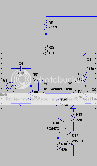
I have made a first schematic with the CFP but no other improvements. I have not added a CCS because I am wondering if it really makes a lot of difference ? As far as I see, it gives some improvements in PSRR and increased OLG but I'm not sure how much these improvements give me in terms of sound quality ? - I didn't see anything significant in the sims.
I also don't have emitter degeneration, the resistors are there for convenience of measuring current balance in the sim. At one point I thought I had pushed the LTP into instability without these resistors so maybe they are important for that alone. But again, nothing significant in the sims.
The distortion performance improved over not having CFP so this is already good. Maybe it's enough.
p.s. Carlos - there is a new transistor a friend of mine has recommended to me for the output transistors so there may be hope of something new that I will post here if it turns out OK.
Attachments
Member
Joined 2009
Paid Member
Emitter Degeneration ?
I need some help with a real newbie question !
Looking at the CFP LTP I can't see a need for the emitter degeneration - which is a popular improvement. First off, the reason to include it is to improve linearity through some local feedback. But the CFP has a built-in level of local feedback already, linearity is already vastly improved. Emitter degeneration is used when you want to drive more current throught the LTP to increase the slew rate (i.e. curent drive into Cdom) but need to pull back the gain this generates. But the CFP nicely uses the 'slave' devices to provide a good increase in current drive to the VAS without pushing up the gm of the input devices. I also find that Self reports most of the gains in linearity from emitter degeneration to occur at 20kHz or above, not in the 'meant and potatoes' range of listening frequencies.
One could say that the degeneration resistors are inexpensive and have no real downsides - but why bother if you don't need them ???
p.s. I don't know how much credence you guys put into the 'memory effect' theory ? [http://peufeu.free.fr/audio/memory/memory-4-circuits.html] which also favours a CFP input stage, but it appears key not to use a current mirror or you lose most of the benefits.
I think the memory distortion theory is very appealing. If I build a new amp, I'll definately make room for both CFP and cascode.
Regarding the difference between JFET/bipolar and bipolar/bipolar, I find J/B more "forward" sounding, having more "texture" and "body". Most of all it adds "presence" and it's more involving. B/B is softer, smoother and a bit vague.
One problem is that the only JFET input transistors I've used are SK170 and SJ74, so I don't really know if it's JFETs in general that sound this way or just the tested transistors. I've tried a lot of different opamps though and I find the ones with JFET input sound different from the ones with bipolar input in the same manner, with one or two exceptions. The downside with JFETs is a grainy and harsh sound, but I think the use of CFP cures a lot of this.
One of the pros with J/B CFP is the low input bias currents so you don't need input capacitors or balancing the pos and neg inputs.
I've also found that CFP input amps are unstable without emitter degeneration in the LTP.
I don't hav any good experience from using current mirrors on the LTP. The distortion is lowered but I don't like the sound.
Member
Joined 2009
Paid Member
Thanks Nelson - a most interesting comparison. I will want to try hearing the differences so I should try and design things to allow me to try both BJT and JFET input.
I had a play with Spice at lunchtime again:
I decided to look more closely at a CCS fed LTP as an option. I'm not sure I see enough benefit, would be grateful for some real-life comparison in term so the sonic benefits of a CCS vs resistive feed to a CFP LTP - anyone ??
One touted benefit of the CCS is a reduced turn-on thump. I tried to simulate this in Spice with zero input and a quick ramp in supply rails. The simulations show how the voltage at the LTP power node rises as the rail filter cap charges up. But the turn-on thump was no different at the output compared with a resistive LTP feed. ??
However, I was able to initiate some nasty oscillations which started some time after the initial turn-on thump.
I found that the LTP oscillations occur only when I have a CCS (a perfect CCS in Spice). With a resistive feed to the LTP there are no oscillations. With emitter degenration of the LTP (33R - 47R wasn't enough, 82R was marginal, 100R OK) there are no oscillations. The triffer was the interaction with the VAS. I see that as the LTP power rail comes up the LTP output voltage ramps away from the -ve rail, as it should. This output feeds the base of the VAS and when the voltage reaches a point where the BE junction of the VAS is forward biassed the LTP oscillations start.
So why do I want a CCS at the top of the LTP ???
edit: attachment shows VAS input (green is CCS loaded LTP, blue is resistor loaded)
Attachments
Gareth,
I'd guess the reason is that you have a phase reversal before the OLG has come back to unity - that is, you have not met the Bode-Nyquist criteria. The fact more degeneration seems to correct it is clear indication your lag compensation may be the problem. Increase Cdom!
In a standard LTP, as one device turns on, the other turns off, with a powerful link between the two. In a CFP LTP, each control device is run at constant current (that is the strength, yielding constant Vbe), and current swings are absorbed in the slave devices. If the collector of each device is connected to the control emitters and the CCS, then there is no feedback from the slave back to the master emitter; you need to signal to the control devices any imbalance by using some degeneration. You don't need much, 10R will do the job, but CFP LTPs in my experience do need it.
Cheers,
Hugh
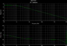
AKSA said:
I'd guess the reason is that you have a phase reversal before the OLG has come back to unity - that is, you have not met the Bode-Nyquist criteria.
Yes, if I may demonstrate on my Havoc amp (has the CFP input). Attached is the correctly degenerated loop gain plot. Emitter R's are 91 ohms each:
Attachments
Member
Joined 2009
Paid Member
Hugh, MJL21193,
You explained it so well that it now seems obvious in hindsight
That 180 degrees kicks in where you don't want it !
So in fact, even if the sims. show no oscillations when using a resistive feed to the LTP, it's likely pretty marginal and guaranteed to ruin the party if I build it like that.
So I got a nice improvement with the CFP front end, better linearity (lower distortion), higher slew rate if I want to crank the current up.
Next stop will be to investigate:
Is there really any more to be gained out of this CFP front-end by adding a CCS ?
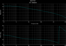
With emitter degenration of the LTP (33R - 47R wasn't enough, 82R was marginal, 100R OK)
Confirmed , I did the Step thing with a CFP LTP @47p Cdom
.STEP PARAM RDG 5 165 40 (starts at 5r , increases by 40 up to 165R)
Replace your LTP resistor values with {RDG}
As the plot shows , at both 5R and 45R , you have too high a UG
freq. (3.1mhz and 1mhz) with insufficient phase margin (almost 0 -180 degrees) with a 5R resistor. As you said 85R ( 600k UG -92 phase) is stable. with 68 Pf (47R - 68R is stable).
OS
Attachments
Member
Joined 2009
Paid Member
Hi OS,
Thanks for checking into it, I can see I'm in good company.
I was surprised how much degeneration I needed when I was manually changing the resistor in the sim (I'll have to try this .step command).
OS, Hugh,
Thing is, I am reluctant to increase Cdom because my listening tests on the TGM1 resulted in me reducing Cdom to 44pF. Of course there's no guarantee that this is the best 'sound' for TGM2. This is an example of where the 'subjective' influences the design.
Another parameter I can look at is the gm of the input devices. Increasing the collector resistance on these would reduce the current and gm a little and give me more flexibility on Cdom/degeneration tradeoff maybe. I can arrange it to keep the total LTP current unchanged so that the reduction in current through the input devices is added to that through their 'slaves'. Does this make sense ?
Attached is something that I think was suggested in your other thread, but that wasn't said again.
Still not a perfect CCS, but I would say it is a trade off between what you want and what others suggest.
Also, pertaining to turnoff thump - I am very surprised no one has said this yet.
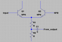
Look at C1 and C2, and the accompanying resistors. The time constants are not the same. This will cause some "thump" if I'm not mistaken.
Look at this schematic. The gain is 10, so the voltage across the feedback network will be 10 times the input voltage. Also, the feedback network has 10 times less resistance (I do this because it increases stability and also decreases distortion by a very insignificant amount - however, there will be offset voltage at the output even on a fully balanced LTP). So multiply the input capacitance by 100 and you have the same time constants. With this configuration, the time constants are the same (unless someone corrects me). Before we try to destroy turn-on thump some other way, I think we should correct this.
Hope this is useful,
- keantoken
Still not a perfect CCS, but I would say it is a trade off between what you want and what others suggest.
Also, pertaining to turnoff thump - I am very surprised no one has said this yet.
Look at C1 and C2, and the accompanying resistors. The time constants are not the same. This will cause some "thump" if I'm not mistaken.
Look at this schematic. The gain is 10, so the voltage across the feedback network will be 10 times the input voltage. Also, the feedback network has 10 times less resistance (I do this because it increases stability and also decreases distortion by a very insignificant amount - however, there will be offset voltage at the output even on a fully balanced LTP). So multiply the input capacitance by 100 and you have the same time constants. With this configuration, the time constants are the same (unless someone corrects me). Before we try to destroy turn-on thump some other way, I think we should correct this.
Hope this is useful,
- keantoken
Attachments
guarantee that this is the best 'sound' for TGM2.
With CFP , the best overall distortion was realized at "balance"
(equal current between slave / master) , play with that B-E resistor.
or step it between 470r - 1.5k to see.
Use this for your main directive :
.param num_fft_pts 1024
.param freq 20k
.param timestep {1/((num_fft_pts-1)*freq)}
.tran 0 1m 0 {timestep}
.options plotwinsize=0 .four {freq} V(c)
Better AC source ... (0 {sqrt (.3)} {freq}) add this as your signal source value.
Make the output of your amp (C) "label net"
Add the .step param Rbe 400 1500 100
make your 2 slave resistors {RBE} ,RUN ... then the spice error log will show distortion for each step (all 11 of them). If you do a FFT of the output (C) , you will also see the harmonic "shift" as you step through the values.
REAL COOL
OS
Member
Joined 2009
Paid Member
Thanks guys, this will keep me busy at the Sims when I next get on it
I knew there was more to this CFP than I saw first time around. I need to upgrade my Spice skills and look at this design more closely. I did briefly look at a balanced master-slave current in the LTP but didn't see an obvious null in distortion. I'll try some of these Spice directives.
Talking of turn-on thump
------------------------------
First off, I don't have a noticeable thump with TGM1, but that doesn't mean there isn't any.
Keantoken - if I understand your point,
At turn-on the VAS and output are woken up as quickly as the psu can charge its caps. To avoid trouble we want the voltages at the bases of the LTP input devices to come up together so that the turn-on transients appear as common-mode input, which is rejected by the LTP before it reaches the VAS. That makes sense to me !
So I look at how quickly the voltages on the bases of the input devices can change.
The input device (Q1) sees the input cap (C1) and the input shunt resistor R1 (+R2, which we can ignore). RC = 0.47uF x 44k = 20.68ms (giving me an input filter with a -3dB at 48Hz).
The feedback device (Q2) sees the input signal ground via the feedback loop of R8 and C2. RC = 22uF x 2.7k = 103ms (suggesting that the feedback loop is not limited my bass response).
They don't match.
I did look at turn-on thump in my sim. I noticed that there was a transient at the output, will have to check but I think it was about 40mV at worse.
What you have said makes perfect sense, and I can modify the design to balance the RCs more closely.
p.s. Bootstrapping wasn't forgotten, but my current aim is to understand the CFP structure a bit more, and see how much improvement a CCS offers for a CFP-LTP.
Yes, you understand perfectly!
Big, SPICE can be an amazing tool for learning electronics. If you want to know something, hook it up in spice - don't get lazy!
I learned practically everything I know about electronics from spice+DIYAudio, in I would say max 3 years.
So as far as learning about the LTP - I did it by simming numerous "Blameless" style class A amplifiers with various tweaks I had come up with. As you screw around you tend to figure out things that would have never occurred to you without all that time tinkering. Time has a strong correlation with experience (although, you must never assume this to be true in all circumstances).
Have fun,
- keantoken
- Status
- This old topic is closed. If you want to reopen this topic, contact a moderator using the "Report Post" button.
- Home
- Amplifiers
- Solid State
- TGM2 amplifier