Looking recently for information to construct a simple set of amplifiers to complete my HTPC amp , I attempted to discuss the issue on the DX thread.
Since I was forced to modify the layout because of my application (stealth amp retrofit) , I could not use the DX board. I also have a surplus of 2sa992's , mje/ and other on- semi devices.
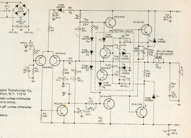
The amp in question was originally an RCA application note (1972)...
http://www.hilberink.nl/amps/amps2.htm
As most of us know , this is the "original" .. skillfully upgraded and modified by "uncle charlie" , aksa , and too many others to count.
Also very interesting is that on the other pages (link above), many of our DIY SS amps found their beginnings in these RCA designs.
This thread is to address ALL modifications that are possible to this simple topology (even minor ones). In other threads it was suggested
that the use of new high Ft devices would render both the sound and stability of this amp unusable AND that if a constructor does modifications,
strays from the path,or asks questions, they will learn nothing !!
I know this to be false , as many clones of the RCA exist of world class performance that DO use modern parts. (I already have 2 that are 1 year old )
Since I was forced to modify the layout because of my application (stealth amp retrofit) , I could not use the DX board. I also have a surplus of 2sa992's , mje/ and other on- semi devices.
The amp in question was originally an RCA application note (1972)...
http://www.hilberink.nl/amps/amps2.htm
As most of us know , this is the "original" .. skillfully upgraded and modified by "uncle charlie" , aksa , and too many others to count.
Also very interesting is that on the other pages (link above), many of our DIY SS amps found their beginnings in these RCA designs.
This thread is to address ALL modifications that are possible to this simple topology (even minor ones). In other threads it was suggested
that the use of new high Ft devices would render both the sound and stability of this amp unusable AND that if a constructor does modifications,
strays from the path,or asks questions, they will learn nothing !!
I know this to be false , as many clones of the RCA exist of world class performance that DO use modern parts. (I already have 2 that are 1 year old
)Member
Joined 2009
Paid Member
By bigun - Do we keep the protection circuit for this thread ?
That is a good question... A properly configured VI limiter can be good for those that are careless.
 At low rails with large speakers , the rail fuses would blow, but at 40-0-40vdc (my version) ,it would most likely damage my small sony surround speakers.
Maybe 2 versions ??
It would be interesting to find the characteristics of the original RCA semi's to see EXACTLY how the "baseline design" performed.
This would allow us to compare the new to the old (FFT , loop gain.etc) , to see what the best mods are to retain the original "flavor". We might find that the old devices DID have limitations (most likely) that our new ones can easily outperform (also most likely).
OS
Nice schematic, i have tried it into the seventies
sound is not good...has more harmonics than a tube amplifiers...measure almost the same but sounds worse than a tube amplifier.
Good that you gonna ressurrect this one..if keep the topologie and recalculate all that one, without placing CCS, mirrors, complementary VAS, tripple darlington, double simetrical differential and all that modern stuff, then you will have a warm and delicious sound with less than 0.03% of harmonic distortion... and beautifull fourier graphic without bars, only the fundamental tone
And this because of the topologie... but keeping the bootstrapp there and re-adjusting it to the entire amplifier.
Good luck, have fun and enjoy
I did it watching the Sony 33 schematic and could finally produce my amplifier..i have tried many possible options and combinations and could not make it better than it has resulted. (to my ears, this is personnal)
There's nothing to learn, it is try and error basis, just ohm law to calculate and to try subcircuits...hard work and swet only.
Maybe you gonna learn that keeping the topologie the way it was before was a very good idea.
regards,
Carlos
Hi, carlos. I am glad to see you.
When you did build the RCA ,did you use the EXACT parts??
These...
RCA1A01 Si npn 5W 70V 4V 1A 200>C 120MHz 40MIN MOT TO39
RCA1A02 Si pnp 7W 50V 4V 1A 200>C 50MHz 30MIN MOT TO39
RCA1A05 Si pnp 5W 75V 4V 1A 200>C 60MHz 50MIN MOT TO39
RCA1A06 Si npn 5W 75V 4V 1A 200>C 120MHz 50MIN MOT TO39
RCA1C05 Si npn 40W 140V 120V 5 4A 200>C 4MHz 40MIN RCA TO66
RCA1C06 Si pnp 40W 140V 120V 5 4A 200>C 10MHz 40MIN RCA TO66
NO intention of adding any "fancy" things here. Just basic reverse engineering. The only thing might be a CCS. the DX's zener "acts" as a crude CCS , rejecting "garbage" from the positive rail. The RCA's diode/R - C also decouples the LTP from the "garbage"(rail).
Also , when you built the RCA , you used the 3 diodes instead of a proper Vbe , which made for bad sound (Xover distortion).
OS
When you did build the RCA ,did you use the EXACT parts??
These...
RCA1A01 Si npn 5W 70V 4V 1A 200>C 120MHz 40MIN MOT TO39
RCA1A02 Si pnp 7W 50V 4V 1A 200>C 50MHz 30MIN MOT TO39
RCA1A05 Si pnp 5W 75V 4V 1A 200>C 60MHz 50MIN MOT TO39
RCA1A06 Si npn 5W 75V 4V 1A 200>C 120MHz 50MIN MOT TO39
RCA1C05 Si npn 40W 140V 120V 5 4A 200>C 4MHz 40MIN RCA TO66
RCA1C06 Si pnp 40W 140V 120V 5 4A 200>C 10MHz 40MIN RCA TO66
You yourself said that the DX could not match the aska in either soundstage or high frequency clarity/detail. (lost these qualities)By DX - could not make it better than it has resulted. (to my ears, this is personnal)
by DX - CCS, mirrors, complementary VAS, tripple darlington, double simetrical differential and all that modern stuff
NO intention of adding any "fancy" things here. Just basic reverse engineering. The only thing might be a CCS. the DX's zener "acts" as a crude CCS , rejecting "garbage" from the positive rail. The RCA's diode/R - C also decouples the LTP from the "garbage"(rail).
Also , when you built the RCA , you used the 3 diodes instead of a proper Vbe , which made for bad sound (Xover distortion).
OS
Member
Joined 2009
Paid Member
By bigun - If I get a chance, I will doodle the topology in LTSpice since people like to play with these things there.
Just a few changes from the DX,TGM. The "trick" is the devices , since it is RCA's design for those devices.
BTW ,On your TGM, what is the LTP current. I did notice , depending on device , the bootstrap/RCA amp has a "window" (.9 to 1ma -2sa992) where the differential becomes balanced , offset goes low, and distortion really drops). This is not the case with the blameless or symasym topologies. Also , I noticed that this amp can keep its low output distortion up to about 2/3rd's peak to peak of the rail voltages , then a big increase in THD (another bootstrap effect)??
Have you seen this errata ?
OS
No.... only some parts were original...i was very poor those early days
as a student i could not buy too much parts.
Some were original, others not...but do not worry with parts..they do not sound...topologie sounds.
Also i do not remember very well what parts i have used..was a very long time ago..but i remember i dislike the sound and had to tweak in something to make it work..the original schematic had not operated properly.....i cannot remember details...just the feeling about the amplifier.
That diode there is an audio killer... after assemble, remove it and place it once again and listen to high level sound... full power, and observe the hell harmonic distortion you gonna listen.
No!.. when trying amplifiers i use no diodes or VBE multiplier, i use resistance into the prototype and i use to take care of the heat as i will not have thermal control.
regards,
Carlos
Well , here is the amp that is supposed to oscillate  ..
..
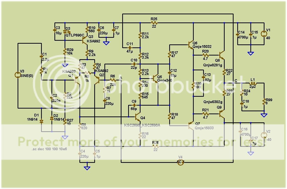
I have 2 of the the NPN LTP version (not as refined), not a problem for a year. Attached is a FULL (models included) .ASC for the above schema. Not a PPM amp , just 9 devices.
A few posts later , either me or BG will "doodle" the original. I also have a PCB layout in the works with integrated DC supply. At 5.5" X 3.5" , it will leave nothing else to build... just hook up the trafo - and enjoy..
Also should be good for multichannel/HT use.
OS
..
I have 2 of the the NPN LTP version (not as refined), not a problem for a year. Attached is a FULL (models included) .ASC for the above schema. Not a PPM amp , just 9 devices.
A few posts later , either me or BG will "doodle" the original. I also have a PCB layout in the works with integrated DC supply. At 5.5" X 3.5" , it will leave nothing else to build... just hook up the trafo - and enjoy..
Also should be good for multichannel/HT use.
OS
Attachments
By DX - Some were original, others not...but do not worry with parts..they do not sound...topologie sounds
Carlos... , You of all people should know it is ALL about the parts !!!

They do not design the circuit and THEN make the transistors to fit the design!! The boring people in their man caves (cubicles) are given the latest, greatest parts from the factory and told to design the best consumer Ceeearrrp... as to sell more factory parts.
(bird before egg / egg before bird??
)OS
Nope... no oscillator .. even with 25' speaker cable and NO zoble.Oh!...is this amplifier oscilating?.... was you that made it?
By DX -No...it is none about the parts
Then , as YOU said ..(MJ- XX ,higher Ft, etc) would oscillate in the DX. If it was only topology , ANY transistor would work..
The one above does NOT oscillate ,
 the evil 22R and extra miller C allowed the high Ft KSA to work. Topology follows the device.
( Bird before egg?? )
OS
Listen this amplifier sound..you will recognize the Dx Amplifier sound
Because this one is using absolutelly the same schematic..some resistances are different, some small differences into the bias current.... i have discovered that schematic monthes ago... a friend has sent it to me.
I have the schematic, but the one gave me (I have asked him please to give me copy) said that he will not be happy watching the schematic published.
So...i have not used this one as reference..but sounds the same..because topologie sounds...the RCA can sound the same if you remove some strange things it has, alike that diode.
I see, Ostripper, that we have strong differences in points of view..so... will let you conduct your thread without my interferences..be happy and enjoy your beliefs.
Bye...next Christmas i will visit you to wish you a happy new year.
Will not waste my time discussing..i have work to do, to people that are tuned with my ideas..you are not.
Parts does not sound..topologie sounds, adjustment of bias, vbe voltages and currents (operation points) sounds..the rest is myth... but a lot of good people use to say parts sounds...i do not use to discuss beliefs, as this is alike religion..no good result.
http://www.youtube.com/watch?v=warJLziW6gkregards,
I hope you recognize the Dx sonics... i think you have assemble one as a toy to your kids to play music, or into the kitchen or somewere into the house... maybe you remember the sonic characteristics of the Dx amplifier..characteristic of this topologie... observe the slew rate, the attack speed into the tones when guitar is playing..awsome!... the topologie...was not me, nor the parts....it uses low speed transistors into some places as drivers and VAS.
Carlos
Sorry, i forgot to show you the topologie
I cannot publish the schematic, but partial and without values i think my friend will not be mad with me....the one sent me the schematic.
This is the Scott model you saw into the youtube video..same topologie, same nice sound.
regards,
Carlos
I cannot publish the schematic, but partial and without values i think my friend will not be mad with me....the one sent me the schematic.
This is the Scott model you saw into the youtube video..same topologie, same nice sound.
regards,
Carlos
Attachments
by DX-I cannot publish the schematic
Thank you, my friend. I see (learned)2 things from your schema (the diodes on the VAS and Vbe).
They seem to be "insurance" to make the design foolproof (2 are thermal for cfp OP - better than P3A).
Actually , both of us are right. A smaller amount of the sound is the part , the topology is dominant. BUT , unless the topology takes the devices into account , you will have less OPTIMAL sound and a possible burnt pile/oscillator (unreliable).
BTW , I am not a blackgate capacitor "believer" , the sounds quality is the LTP balance + compensation. While the local feedback of the bootstrap is also a MAJOR effect , A high quality standard cap will give you 95% satisfaction.
OS
Member
Joined 2009
Paid Member
ostripper said:
Just a few changes from the DX,TGM. The "trick" is the devices , since it is RCA's design for those devices.
BTW ,On your TGM, what is the LTP current. I did notice , depending on device , the bootstrap/RCA amp has a "window" (.9 to 1ma -2sa992) where the differential becomes balanced , offset goes low, and distortion really drops). This is not the case with the blameless or symasym topologies. Also , I noticed that this amp can keep its low output distortion up to about 2/3rd's peak to peak of the rail voltages , then a big increase in THD (another bootstrap effect)??
Have you seen this errata ?
OS
The TGM amplifier will work fine with a range of LTP currents, down below 0.9mA for example. The issue is not to allow it to be so unbalanced that you destroy the waveform, you see this quickly even in a dc operating point simulation. The current at which the LTP is well balanced depends on the collector load resistor of the input device, which we are free to adjust over a certain range; it also depends a bit on the device models. I think the 'window' you suggest is a good starting point for this thread.
I haven't looked at distortion with output close to the rails, we will try this in the sims to start. TGM with +/-15V p-p output swing looks nice and clean distortion wise.
Here's the schematic into spice, please check for errors. Then I will post the actual file.
It doesn't work as-is because it uses default library for the active devices and so it isn't going to balance. Check it first - but I think the LTP is so out of balance that this must be fixed.
Attachments
Member
Joined 2009
Paid Member
ostripper said:BTW , I am not a blackgate capacitor "believer" , the sounds quality is the LTP balance + compensation. While the local feedback of the bootstrap is also a MAJOR effect , A high quality standard cap will give you 95% satisfaction.
OS
There should be some compromises on parts selection. As with most things in life, you pay a bit more and you get something better but at some point you have to pay a helluva lot more to get not much extra. It's the care in which all the parts are selected, some parts are not so critical and others can make a difference. Listening tests can help, not the simulations.
By Bigun -Here's the schematic into spice, please check for errors. Then I will post the actual file.
Looks correct , Gareth.
I will find the closest devices to the RCA's that I can and post a .ZIP with their models.
On the topic of high output distortion , after that 2/3rd's "point" THD
stays .1% all the way up to actual clipping and is almost exclusively H2 in content. I suspect this is the reason for the pleasant bass or the perception of "better bass" , especially at high levels.
I "looked" into the bootstrap cap as I increased the level and saw both phase and level changes within. It should be cool to see the plot of this while stepping the input. (next)
OS
- Status
- This old topic is closed. If you want to reopen this topic, contact a moderator using the "Report Post" button.
- Home
- Amplifiers
- Solid State
- RCA 1972 Basic amplifier MODS