Ok, I said that I would not post on this again until I actually built one and tried it out. So I did. This is a work in progress and I’m sure a couple of warts will show up and there is some tweaking to do. Hopefully I’m not missing anything fatal ") .
.
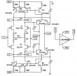
This is what I like to think of as a signal path based on pair-wise matching rather than absolute parameters. I was able to strip out a lot of components from the original circuit. The self biasing FET input lights up the whole thing at about 5mA a leg, the bipolars were pulled right out of the bin without matching (though they are from one lot). The bipolars basically make up a CMCL and differential VAS at the same time. Returning C1/C4 to ground greatly improves PSRR. I used an LME49600 as an output stage for simplicity this time (thanks Sigurd). You can vary R1-R5 for different input gm, bias, and linearity. The 2K resistors “sop up” random offsets, without them the DC solution is singular somewhere for any offset voltage on the diff-pairs. You can also probably get away with Q3 and Q8 as 1N4148’s as well as varying the VAS bias via their associated resistors.
In a second post there is a picture of a simple test circuit (to magnify the input error signal) and a scope photo. Excuse the cell phone pic and ignore the top trace. The picture is a DC crossplot of the input error vs output voltage with a scale of 2V per div horizontal and 20uV per div vertical. That means one box is an Aol of 10^6 so here we have ~5X that. Even with a several percent FET mismatch I was able, with the two trims, to trim both offset and gain to near perfection. Interesting to note the 2k resistors do not effect Aol which could be trimmed from plus a lot through “infinite” and out again to minus a lot. I have not done exhaustive testing but it appears that there is also a very strong null of THD and it remains to be seen if all three are coincident. In the end it does not matter if the Aol is “infinite” at the same point that the THD is minimum. Of course everything drifts around and some kind of thermal attachment of the pairs is needed.
Not pictured is a quick test as a 20dB stage driving 100 Ohms || 1000pF. The +-15V .5A lab brick that I was using did not look pretty so no final THD until I get a new supply, but everything looked “eyeball” OK (no oscillations or overdrive problems) even at 24pF on all 4 comp caps. Glen, I tried a full 10% mismatch on C2/C3 and no “VAS’s gegen VAS’s” just a tiny increase in seconds. This BB is fully socketed BTW so it is a bit of a mess. I was actually surprised at the 1000pF being almost invisible here.
Well, so what? For one virtually all non-linear device capacitances/conductances are reduced (or made common mode errors) by first order by subtraction, no cascodes and their biasing needed . A fairly low device count to get an almost ideal gm/C transfer function as well as PSRR highly enhanced by the symmetry.
As an additional note you can bootstrap the bottom of C1/C4 ala the 797 and achieve the same output stage distortion removal. This is a little harder to in this case since you need pick off the input-output voltage of the buffer.
.This is what I like to think of as a signal path based on pair-wise matching rather than absolute parameters. I was able to strip out a lot of components from the original circuit. The self biasing FET input lights up the whole thing at about 5mA a leg, the bipolars were pulled right out of the bin without matching (though they are from one lot). The bipolars basically make up a CMCL and differential VAS at the same time. Returning C1/C4 to ground greatly improves PSRR. I used an LME49600 as an output stage for simplicity this time (thanks Sigurd). You can vary R1-R5 for different input gm, bias, and linearity. The 2K resistors “sop up” random offsets, without them the DC solution is singular somewhere for any offset voltage on the diff-pairs. You can also probably get away with Q3 and Q8 as 1N4148’s as well as varying the VAS bias via their associated resistors.
In a second post there is a picture of a simple test circuit (to magnify the input error signal) and a scope photo. Excuse the cell phone pic and ignore the top trace. The picture is a DC crossplot of the input error vs output voltage with a scale of 2V per div horizontal and 20uV per div vertical. That means one box is an Aol of 10^6 so here we have ~5X that. Even with a several percent FET mismatch I was able, with the two trims, to trim both offset and gain to near perfection. Interesting to note the 2k resistors do not effect Aol which could be trimmed from plus a lot through “infinite” and out again to minus a lot. I have not done exhaustive testing but it appears that there is also a very strong null of THD and it remains to be seen if all three are coincident. In the end it does not matter if the Aol is “infinite” at the same point that the THD is minimum. Of course everything drifts around and some kind of thermal attachment of the pairs is needed.
Not pictured is a quick test as a 20dB stage driving 100 Ohms || 1000pF. The +-15V .5A lab brick that I was using did not look pretty so no final THD until I get a new supply, but everything looked “eyeball” OK (no oscillations or overdrive problems) even at 24pF on all 4 comp caps. Glen, I tried a full 10% mismatch on C2/C3 and no “VAS’s gegen VAS’s” just a tiny increase in seconds. This BB is fully socketed BTW so it is a bit of a mess. I was actually surprised at the 1000pF being almost invisible here.
Well, so what? For one virtually all non-linear device capacitances/conductances are reduced (or made common mode errors) by first order by subtraction, no cascodes and their biasing needed . A fairly low device count to get an almost ideal gm/C transfer function as well as PSRR highly enhanced by the symmetry.
As an additional note you can bootstrap the bottom of C1/C4 ala the 797 and achieve the same output stage distortion removal. This is a little harder to in this case since you need pick off the input-output voltage of the buffer.
Attachments
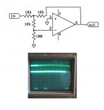
scott wurcer said:Picture of DC input/output transfer function.
Any scale?
Congratulations Scott! I would bolt all FETS together and put the whole thingy in a freezer, then in a kitchen oven, to get a clear drift picture.
Now you need a linearized output stage. No need for huge input resistance, let it be just flat and linear: do you need an infinity DC gain for audio? Also, you may sacrifice output voltage capabilities in order to bootstrap emitter followers. One way I would consider, is a feed-forward bootstrap by a JFET on top of BJT, with gate connected to base.
Now you need a linearized output stage. No need for huge input resistance, let it be just flat and linear: do you need an infinity DC gain for audio? Also, you may sacrifice output voltage capabilities in order to bootstrap emitter followers. One way I would consider, is a feed-forward bootstrap by a JFET on top of BJT, with gate connected to base.
stinius said:Thanks Scott very nice
And no “VAS’s gegen VAS’s”
It’s a very impressive circuit.
Could you post the values on the R1-R5?
I just stuck 50 Ohms in for each to get the DC about right, far from optimum but the performance is actually pretty resillient to changing values. The Aol trimming was just an exercise to see if FET matching made any difference. I satisfied myself that one could trim independently two parameters with the pots provided. If offset is one then you could pick THD or Aol and for even casually matched FET's you could trim two perfectly. I have not done an exhaustive study but it looks that way. I don't like the low value pots in the signal path i.e. trimming the 50 Ohm resistors.
I will play with this some more this weekend.
Jams idea should work too and gets the circuit even simpler but now it seems the PSRR also is sensitive to the trim meaning there are not enough degrees of freedom to optimize everything.
The little heatsinks from the group buy need a new layout unfortunately, but I might bend the leads on some pairs and try it out anyway.
scott wurcer said:Glen, I tried a full 10% mismatch on C2/C3 and no “VAS’s gegen VAS’s” just a tiny increase in seconds.
That is thanks to those 2k resistors
. I'm curious as to the square wave response resulting from the frequency compensation employed - you've got a doublet of dissimilar poles in the open loop response there.The inverter sims are textbook clean but the follower responses have a little settling hook due to some common mode effects. This only shows up over 10V p-p. I'll try again to find all the warts and also actually measure the THD into 100 Ohms (I was going to use two of these for my Sennheisers). The next project was to try this with an output stage with gain for around 20W out.
OK. I know that if you use this type of compensation in a non-complementary LTP circuit with a differential, current mirror 'loaded' VAS (Miller on one side, shunt on the other) you get an odd square wave response. Maybe in a fully symmetrical implementation it balances out somehow?
scott wurcer said:Ok, I said that I would not post on this again until I actually built one and tried it out. So I did. This is a work in progress and I’m sure a couple of warts will show up and there is some tweaking to do. Hopefully I’m not missing anything fatal
------
Well, so what? For one virtually all non-linear device capacitances/conductances are reduced (or made common mode errors) by first order by subtraction, no cascodes and their biasing needed . A fairly low device count to get an almost ideal gm/C transfer function as well as PSRR highly enhanced by the symmetry.
As an additional note you can bootstrap the bottom of C1/C4 ala the 797 and achieve the same output stage distortion removal. This is a little harder to in this case since you need pick off the input-output voltage of the buffer.
PMA said:Looks quite perfect.
> Looks quite perfect. (PMA)
Scott, just as PMA, I thinks this circuit is too advanced to understand at first sight.
So, I will not pretend I have tried to see the subtle good things in it, yet.
But because I trust you and know a bit about you
I also know you wouldnt post a shiiittyy circuit
I have to agree with Pavel in my own true way:
Thanks ... it is not everyday we get such a diy project submitted.
From a good guy who is/has been a professional designer of worldwide known Hifi Op-Amps.
I, Lineup, will of course, download your kindly submitted circuit.
I will try to see where your approach differs to usual ways to build
such differtential Voltage Amplifier stages (with buffer option)
yours
Line 'linie' Lineup - does not resort to saying 'NICE' to something he doesnt understand.. yet .. or know about.. yet
And - Lineup is not one hasbie or newbie.
Lineup really exists today and does some amplifier work + explorations
Come mothers and fathers
Throughout the land
And don't criticize What you can't understand
Your sons and your daughters Are beyond your command
Your old road is Rapidly agin'.
Please get out of the new one, If you can't lend your hand
For the times they are a-changin'.
http://www.bobdylan.com/#/songs/times-they-are-changin
stinius said:Hi Scott
I have done some simulations in Pspice, and it seems a bit ”funky” could you please post the whole circuit with all values or drop me an email with it?
Cheers
OK, I'm taking a couple more forced days off I'll try to put something together.
- Status
- This old topic is closed. If you want to reopen this topic, contact a moderator using the "Report Post" button.
- Home
- Amplifiers
- Solid State
- Return of my differential VAS