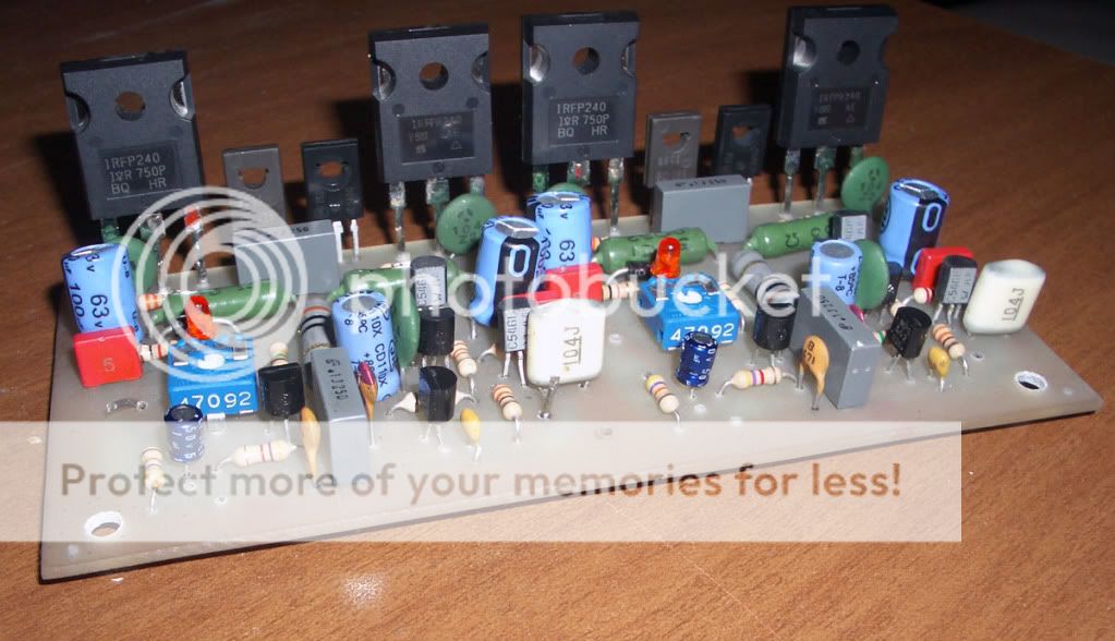
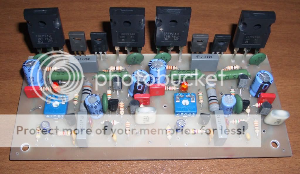
Hi, I just finished assembling this amplifier based on this project.
http://www.redcircuits.com/Page100.htm
I plugged it all but feel the music just croak the mosfet fortunately no heat and no feel smell of burning.
On series of 220v I connecteda 220v 60W light bulb to limit the current, turning the trimmer does not change anything ...
any ideas?
thanks
http://www.redcircuits.com/Page100.htm
I plugged it all but feel the music just croak the mosfet fortunately no heat and no feel smell of burning.
On series of 220v I connecteda 220v 60W light bulb to limit the current, turning the trimmer does not change anything ...
any ideas?
thanks
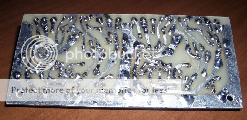
The most obvious thing is r14/15, those should be .33 ohm ,not 33R. Nice hand made layout , thought I was only one who did that (besides carlos - DX).
OS
edit: another issue, even if you get it to amplify with the resistors,the circuit calls for lateral mosfets(it lies!!). All is not lost , you could make a small daughtercard with cap, 2 resistors, trimmer and Bd139/mje340 to give thermal stability.
OS
edit: another issue, even if you get it to amplify with the resistors,the circuit calls for lateral mosfets(it lies!!). All is not lost , you could make a small daughtercard with cap, 2 resistors, trimmer and Bd139/mje340 to give thermal stability.
ostripper said:The most obvious thing is r14/15, those should be .33 ohm ,not 33R. Nice hand made layout , thought I was only one who did that (besides carlos - DX).
OS
edit: another issue, even if you get it to amplify with the resistors,the circuit calls for lateral mosfets(it lies!!). All is not lost , you could make a small daughtercard with cap, 2 resistors, trimmer and Bd139/mje340 to give thermal stability.
I agree tomorrow will replace these resistors, although I think that is not the only error.
thanks
A.
the parts list is wrong.
Do not reduce the source resistors just yet.
You may damage the output devices if you can get sufficient current to turn them on.
The circuit shown in the schematic is designed to ONLY suit Lateral MOSFETs.
It MUST be REDESIGNED to suit Vertical MOSFETs.
Have alook at Vgs for the irf240 and irf9240 that you have fitted.
Now measure the bias voltage you are applying across the gates.
It will not work as is, because the wrong devices have been listed in the parts list.
AndrewT said:the parts list is wrong.
Do not reduce the source resistors just yet.
You may damage the output devices if you can get sufficient current to turn them on.
The circuit shown in the schematic is designed to ONLY suit Lateral MOSFETs.
It MUST be REDESIGNED to suit Vertical MOSFETs.
Have alook at Vgs for the irf240 and irf9240 that you have fitted.
Now measure the bias voltage you are applying across the gates.
It will not work as is, because the wrong devices have been listed in the parts list.
want to say that this amp will not work ever?
I did not understand what I should do, change what?
I also have a doubt about diode 1n4007 and LED
I fear that I have mounted on the contrary.
thanks
Andrew is right , for the IRF's a major redesign would be in order , a proper active Vbias circuit + driver stage would be needed. take a look at the quasi line of DIY amps , they use just IRFP240's , but they are proven designs.
http://www.diyaudio.com/forums/showthread.php?s=&threadid=43331
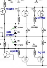
For what you have made, besides the resistors , just jumper the led and diode , leave the trimmer , use 2SK1058/2SJ162 lateral's.
Attached is a similar Op stage to yours the way it should be. (really works).
OS
http://www.diyaudio.com/forums/showthread.php?s=&threadid=43331
For what you have made, besides the resistors , just jumper the led and diode , leave the trimmer , use 2SK1058/2SJ162 lateral's.
Attached is a similar Op stage to yours the way it should be. (really works).
OS
Attachments
ostripper said:Andrew is right , for the IRF's a major redesign would be in order , a proper active Vbias circuit + driver stage would be needed. take a look at the quasi line of DIY amps , they use just IRFP240's , but they are proven designs.
http://www.diyaudio.com/forums/showthread.php?s=&threadid=43331
For what you have made, besides the resistors , just jumper the led and diode , leave the trimmer , use 2SK1058/2SJ162 lateral's.
Attached is a similar Op stage to yours the way it should be. (really works).
OS
I do not understand what the project is completely wrong? will not work ever? in other words this ampli whith mosfet IRFP240/9240 can not be built?
with your modification you've redesigned everything.
I do not understand why I have to add another 2 mosfet
or your changes are only to improve?
thanks
I do not understand why I have to add another 2 mosfet
That was just to show you the "way" , you don't have to use 2 pairs of devices!!
IRF's increase current with heat , so they need something to negate this effect. With a HUGE heatsink , you might get away with it.
Slideman uses the to-220 irf's , they would work with a huge HS, but the big 240's would soon go into runaway.
 .
.OS
I agree the bias cct is not good enough for vertical MOSFET's.
It needs a Vbe or Vgs multiplier.
The MOSFETs wont turn on until there is about 6.5 volts across the bias cct.
I have 3 amps with IRFP devices in them but use big heatsinks and fans and Vbe multiplier to stop thermal runaway.
I wouldnt recommend firing the amp up with no heatsink !
Also look out for a DC offset on the output with the IRFP devices.
I usually get 1.2 volts DC offset before I trim it out. This can make the MOSFET's heat up quickly too when a speaker is connected.
The amp should work as the cct stands but obviously will have thermal issues.
Some notes:
- With R17 indicated value we get a damping factor of about 36 in 8 ohms load.
- Input filter is about 72KHz at +3db
- Where is the temperature compensation (since low value R14 and R15 with low bias current)? As Andrew says the design could have been intended for laterals but the 500 ohms pots (with Led and diode) with about 17ma VAS current suggests it is really designed for higher VGS like verticals...
An output stage using vertical mosfets such as IRF240 etc. will thermally run away very quickly if there isn't intimate thermal feedback. The only exeption is if the amplifier was run in pure class B mode where there is a complete lack of bias current.
Even small (initially) bias currents will begin the thermal runaway event. Ironically you can have too big a heatsink if the thermal sensing device (Vbe) is located far from the output stage. I learnt this the hard way on an early version of an Actrk600 mounted on massive heatsinks but with a thermal feedback loop that was too long. A seemingly healthy bias climbed to a destructive level in a few seconds and blew the ouput devices before I could reach the power switch.
Ouch.
So always use a Vbe or other thermal sense mounted very close to the output stage.
Cheers
Q
quasi said:Even small (initially) bias currents will begin the thermal runaway event. Cheers
Q [/B]
I have run IRFP amps with no heatsinks and had no problems at small audio levels.
However if the DC offset is high or the bias is set too high they will quickly destroy themselves.
I dont set the bias to a set current I just set it just high enough to get rid of crossover distortion and have no problems.
Good italian photos and circuit.
http://www.redcircuits.com/Page100.htm
Sometimes RedCircuits is real great stuff.
however getting 60 Watt or even 90 Watt/4ohm into one amplifier
takes a lot of care .. trying using such very basic and simple design.
You really should be knowing what you are doing man!!
Good that you are posting here to get some comments and good piece of advice
- on this one with only one single pair of IRFP240 + IRFP9240
Good luck, I say")
/LUp
http://www.redcircuits.com/Page100.htm
Sometimes RedCircuits is real great stuff.
however getting 60 Watt or even 90 Watt/4ohm into one amplifier
takes a lot of care .. trying using such very basic and simple design.
You really should be knowing what you are doing man!!
Good that you are posting here to get some comments and good piece of advice
- on this one with only one single pair of IRFP240 + IRFP9240
Good luck, I say
/LUp
thanks to everyone for their help and comments.
I can tell you that I changed the two resistors R14 and R15 at hom .33 and I removed the diode and LED, and now it works quite well.
the problem is reflected in a perceptible distortion and low volume amplification, the amplifier is driven with a transformer with 15v 2nd
I will show you more photos and analysis.
thanks
xcicc said:thanks to everyone for their help and comments.
I can tell you that I changed the two resistors R14 and R15 at hom .33 and I removed the diode and LED, and now it works quite well.
the problem is reflected in a perceptible distortion and low volume amplification, the amplifier is driven with a transformer with 15v 2nd
I will show you more photos and analysis.
thanks
Have you set the bias correctly ?
I have a 1volt ac sine wave going in and monitor the output on a scope. I tweak the bias pot until the sine wave becomes pure.
My IRFP amp needs about 6 volts bias before the sine wave becomes pure.
nigelwright7557 said:
Have you set the bias correctly ?
I have a 1volt ac sine wave going in and monitor the output on a scope. I tweak the bias pot until the sine wave becomes pure.
My IRFP amp needs about 6 volts bias before the sine wave becomes pure.
I have not done the measurements, this weekend I will do the tests.
unfortunately I do not have the scope but only a tester and generator frequencies and much imagination ...
thanks
xcicc said:
I have not done the measurements, this weekend I will do the tests.
unfortunately I do not have the scope but only a tester and generator frequencies and much imagination ...
thanks
I find I can do it roughly by starting off with bias as low as possible and playing music.
To start with the music is distorted until you tweak the bias to the correct point slowly.
- Status
- This old topic is closed. If you want to reopen this topic, contact a moderator using the "Report Post" button.
- Home
- Amplifiers
- Solid State
- new ampli with IRF240