Gettin' better with the output follower MOS
.
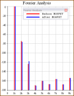
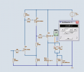
adding a fix for more John Curlish output
via the MOSFET (note! mos still not within feedback)
Now we are talking!
Suddenly the input stage will totally dominate the harmonics
.
adding a fix for more John Curlish output
via the MOSFET (note! mos still not within feedback)
Now we are talking!
Suddenly the input stage will totally dominate the harmonics
Attachments
Hi Lineup,
First thank you for sharing your ideas here ... i just followed youre thread, since im on the go for a diy amp for my new cans (AKG K702) They have an impedance of 62 Ohms so i guess they'll fit well to this amp ...
My question:
Will this circuit work also perfect with a power supply lower than 24 VDC ? How low could someone go, that it still works that good ?
Thx in advance for your reply
regards
artQuake
lineup,
your deep sorrow really does elicit sympathy. Time certainly softens grief through the change we undergo, but some wounds never heal. Hopefully, you can find the strength to go on, bustling with activity is probably the best way.
The recent design version is much cleaner, that ugly comp cap and diode are gone, but R5 could have a value around 100 Ohms and I would run the JFETs at considerably larger current, using types with high Idss here.
IRF610 is an easy-to-find nonlinear device and it does not get more linear by the load. Improvements are possible.
 dear friends in audio
This is a remarkable milestone.
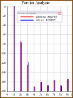
Because first time ever actually one transistor stage shows (a virtual)
improvement of signal.
Some harmonics are improved after passing one mosfet.
Am I going carzy or what the fook?
Maybe my software are trying to play jokes I can not believe in.
Any explainations, of course, are most welcome
At your service - for free, Lineup 58
Attachments
lineup said:Of course, me and other DiyAudio guys will answer any questions
and guide you perfectly on your way towards a very well sounding amplifer.
No matter what headphones you use.
Well, are there any suggestions about the lower PSU-Voltage or was it such a dumb question to overlook it ?
You should be able to use as low as 9 or 12 or 18 VDC.
9 Volt Battery is not suitable. Not as ithis ciecuit is.
Because this draws 360 mA per channel
... one alkali 9 Volt Batt would be empty 2-4 hours like.
15, 18 or 12 Volt DC and thereabout
All you need to do is adjust 440 Ohm resistor
... you increase this value by using one 1k (1.000) trimpot
until you have output at around 40-50% = 5-6 VDC.
See this post:
4. Red resistor 440 ohm sets the output to Close 12 Volt (50% of V+24V)
Temporarily you can use one 1k trimpot to find out what you need.
Start at setting the trimmer at 50% and work from there.
This is an asjustament done to suit for your 2N3819.
JFETs have a bit different parameters for each and every single Transistor we buy
---
But better
you could try my HIFI Class A transistor Headphones Amo
especially designed for 12V.
I myself has got one stereo prototype built fo 15 years ago. Still sounding excellent.
This one really sings in your ears
It has been built by some guys in our forum and even I think some guy made and built PCB card for it:
Solid State >Discrete Single End TRUE Class A HeadPhone Amplifier
PCB by Nordic
Here Stereo, 2 Channels, PCB made by Nordic:
http://www.diyaudio.com/forums/attachment.php?s=&postid=1223649&stamp=1180701258
Regards
lineup said:
4. Red resistor 440 ohm sets the output to Close 12 Volt (50% of V+24V)
It is very suboptimal for a source (or emitter follower) loaded on resistor. Guess, why?
lineup said:
Ask Wavebourn!
He is using same type of circuit idea in his headphone amplifiers ...
Sorry, my circuit idea was a bit different: to load the preamp on more linear input resistance of the output follower, and to load a follower on a counter-modulated current source. As the result, the whole thingy had less distortions, especially high order ones, and the order of them as well as level of them goes down as sounds decay, that's why they are inaudible.
Version 7b .. with 1N4148 diode
.
Version 7b .. with 1N4148 diode
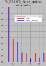
Fourier analys of output from version 7b.
This version I have put the 1N4148 back.
The reason is it makes BC560C stage, bipolar,
act more in a current mirror mode.
This changes the harmonics content of circuit.
The characteristics will lean more to the JFET.
The input N JFET, in this case I use one 7mA BF245B.
This is a HF radio FET that can be found to buy.
The digram
Analys is compared before & after the 2 parallelled output polarized Capacitors.
We can see they do not hardly distort anything.
They possibly will add a tiny bit higher 2nd order harmonics dist.
More specifically you can see this in my image as 6th and 8th.
- The output level is as usual 1 first mW into 32 Ohm.
- PSU is 12 VDC (was asked for)
- DC level before output caps is set to 6.75 VDC .. for this test.
/yours Linie
.
Version 7b .. with 1N4148 diode
Fourier analys of output from version 7b.
This version I have put the 1N4148 back.
The reason is it makes BC560C stage, bipolar,
act more in a current mirror mode.
This changes the harmonics content of circuit.
The characteristics will lean more to the JFET.
The input N JFET, in this case I use one 7mA BF245B.
This is a HF radio FET that can be found to buy.
The digram
Analys is compared before & after the 2 parallelled output polarized Capacitors.
We can see they do not hardly distort anything.
They possibly will add a tiny bit higher 2nd order harmonics dist.
More specifically you can see this in my image as 6th and 8th.
- The output level is as usual 1 first mW into 32 Ohm.
- PSU is 12 VDC (was asked for)
- DC level before output caps is set to 6.75 VDC .. for this test.
/yours Linie
Attachments
Lumba Ogir
Just dont tell me what to do.
tank u
Just because you are not lucky to have a good sim
does not mean we all, that like to use them, should do like you
If you prefer your imagination, which is much more virtual than a good simulator of reality,
then this is your own decision
horrible if we edcuated out pilots for passenger airplanes
in imagnary & hypotetic models, just out of human subjective thinking.
I would not want to ride in such a plane.
I prefer those that has excercised emergency situations baed on matemaical virtual softwares.
Modelas of reality.
I get you do not even use roadmaps .. but does this make easier for you to find your way.
And you do not look at local weather forecast, cretaed by simulations of real data from stations.
A roadmap is a virtual representation of reality.
And it works well. Do you have a car?
Same with the precision tools we use to represent electronical circuits.
They are based on real data, often a good average of the qualities of real components.
Imagniation & unprofeed hypotesis can be fun for you
but let's separate facts & figures from subjective an not validated thinking about real circuits.
They are often much less valid than the models I use here.
I end here with my weather forecast in first post.
It tuns out it came true. Not dificult to know this in advance.
It was based on empirical observations od www.diyaudio.com reality
thanks
linie - lineup
Just dont tell me what to do.
tank u
Just because you are not lucky to have a good sim
does not mean we all, that like to use them, should do like you
If you prefer your imagination, which is much more virtual than a good simulator of reality,
then this is your own decision
horrible if we edcuated out pilots for passenger airplanes
in imagnary & hypotetic models, just out of human subjective thinking.
I would not want to ride in such a plane.
I prefer those that has excercised emergency situations baed on matemaical virtual softwares.
Modelas of reality.
I get you do not even use roadmaps .. but does this make easier for you to find your way.
And you do not look at local weather forecast, cretaed by simulations of real data from stations.
A roadmap is a virtual representation of reality.
And it works well. Do you have a car?
Same with the precision tools we use to represent electronical circuits.
They are based on real data, often a good average of the qualities of real components.
Imagniation & unprofeed hypotesis can be fun for you
but let's separate facts & figures from subjective an not validated thinking about real circuits.
They are often much less valid than the models I use here.
I end here with my weather forecast in first post.
It tuns out it came true. Not dificult to know this in advance.
It was based on empirical observations od www.diyaudio.com reality
Be back with schematics, AC-analyses and Fourier for discussion/evaluation.
All is properly tested in virtual circuit with some of the best instruments we can find.
On the commercial ground my simulator costs way too much.
---
From this we can forsee, that this topic will not discuss my circuit.
But people will do more postings of the usual debate on using sims, paper or calculator
or design by listening to transistors output through headphones of different qualities
after throwing it quickly together with solder.
thanks
linie - lineup
lineup,
Wasted money.On the commercial ground my simulator costs way too much.
.
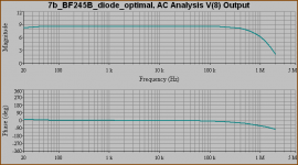
AC Analysis of Version 7b (with diode optimized output).
The GBW (voltage gain x upper bandwidth limit)
of this version is = 29 MHz
Closed loop Gain = 6.50
Closed loop max stable Bandwidth = 4.50 MHz
I decided to use 33p Miller to get the upper freq to rolloff at 1.2 MHz.
By doing this I do not need so heavey a filter at input of JFET
and so risc some corruptions of frequency curve, because of how I adjust My volume pot.
After all I am not designing ShortWave radio circuit here,
but a real Hifi Headphones amplifier
conerning with good reproduction of audioband: Max 20.000 Hertz (=0.020 MHz).
Not much to comment else. But if you have any questions I may consider answer you.
Trolls like Lumba can be at times
and other destroyers of my good threads .. dont bother, please
I will try to ignore stupid comments as much as my mind allows me.
/lineup the cool guy .. at least this morning
AC Analysis of Version 7b (with diode optimized output).
The GBW (voltage gain x upper bandwidth limit)
of this version is = 29 MHz
Closed loop Gain = 6.50
Closed loop max stable Bandwidth = 4.50 MHz
I decided to use 33p Miller to get the upper freq to rolloff at 1.2 MHz.
By doing this I do not need so heavey a filter at input of JFET
and so risc some corruptions of frequency curve, because of how I adjust My volume pot.
After all I am not designing ShortWave radio circuit here,
but a real Hifi Headphones amplifier
conerning with good reproduction of audioband: Max 20.000 Hertz (=0.020 MHz).
Not much to comment else. But if you have any questions I may consider answer you.
Trolls like Lumba can be at times
and other destroyers of my good threads .. dont bother, please
I will try to ignore stupid comments as much as my mind allows me.
/lineup
the cool guy .. at least this morningAttachments

lineup,
A woeful decision.I decided to use 33p Miller
Hi Lineup,
I just soldered the following amp for my cans ... since i had all parts available here it was a short run ... very impressive how powerfull it is ... Driving 40 Ohms (Sony), 62 Ohms (AKG), as well as Senns @ 600 Ohms ... i very content with it ... son now the finish of the enclosure and all will need about a ten or twenty times more time then the soldering ... pah ...
Have a peak :
Schematic
Source
I found the link from a post from you here in the forum ...
So thanx for the hint.
EDIT:
BTW i forgot to say ... this amp can make'em sound really loud !
regards
artQuake
12 Volt operation
For 12 volt operation
we can start thinking 2SK170BL or 2SK170GR
.. in fact in my 12 volt version I used 2SK170BL
running at like 0.5mA for input.
For 24 V .. the 2SK170 might give a little too high voltage gain
.. especially for 16/32 Ohms phones.
For 12 Volt and 32 Ohms .. 2SK170 input like in my design here
will work very well.
/line 'linie' lineup one designer
For 12 volt operation
we can start thinking 2SK170BL or 2SK170GR
.. in fact in my 12 volt version I used 2SK170BL
running at like 0.5mA for input.
For 24 V .. the 2SK170 might give a little too high voltage gain
.. especially for 16/32 Ohms phones.
For 12 Volt and 32 Ohms .. 2SK170 input like in my design here
will work very well.
/line 'linie' lineup
one designer2SK170BL JFET Headphone for 12 Volt DC
.
My recommended circuit for 12 VDC.
Phreaking low distortion !!!!
if you can find one optimal resistor: R4=96.5 Ohm
Because this base stopper removes a lot of 2nd harmonics dist
in output stage.
Changes:
1. JFET 2SK170BL (IDSS=8mA) set at 0.5mA operation
2. ZVP3306 ZETEX great TO-92 P-MOS, set at 10 mA operation
3. BD140-16 as output for 120 mA bjt Class A operation,
into 33 Ohm power resistor
Enjoy !!!
Attachments
- Status
- This old topic is closed. If you want to reopen this topic, contact a moderator using the "Report Post" button.
- Home
- Amplifiers
- Solid State
- 3T HeadPh Amp. JFET-BJT-MOSFET