Hey guys, i apologize if this isnt audio exactly, but it has to do with transistors which i know is involved with audio amplification.
I am wondering if this is correct:
i am wanting to fully saturate the transistor (2N4401, Ic max = 600mA, Hfe min = 40). the base will be at a variable voltage; as temp increases, so does the voltage; this voltage is off of a set of fans.
The reason being that i want to make this is because no matter what the voltage is between 7-12volts, i want the output to the computer fan be 12 volts.
Thank you for your time!
I am wondering if this is correct:
i am wanting to fully saturate the transistor (2N4401, Ic max = 600mA, Hfe min = 40). the base will be at a variable voltage; as temp increases, so does the voltage; this voltage is off of a set of fans.
The reason being that i want to make this is because no matter what the voltage is between 7-12volts, i want the output to the computer fan be 12 volts.
An externally hosted image should be here but it was not working when we last tested it.
Thank you for your time!
Transistor must be a big one, because each fan will drain 200 miliamperes
this means power and heat.... heatsink gonna be needed too.
Use a diode from base to emitter...to protect your base to emitter junction against over voltage.... you do not need to enter with all that voltage....less than 1 volt, with a very small current, will turn the transistor on.
So, use that current limiting resistance you have installed into the base, but install a diode with arrow pointing down.... not a very small diode...use a 1 ampere one for safety reasons.... more reliable.
this way voltage gonna be controled by the diode... it will keep voltage into the base sligtly bigger than 600 milivolts, but will not allow base to have bigger than that
Transistor, into saturation mode (switch "on") will have a voltage from coletor to emitter (saturation voltage).... this voltage will reduce, sligtly, your voltage to the fans.... voltage will be reduce by almost 0.5 volt
regards,
Carlos
Attachments

Thank you for the reply.
I have a few questions:
1.) About the size of the transistor: The fan I will be operating will pull 260mA @ 12 volts. The noise isnt a factor because this will be inside of an Xbox 360. The DVD drive will be WAY more noisy than the fan will ever be so noise isnt really a factor. I am putting a fan directly over the CPU and extended graphics processor heat sink; that thing gets burning hot when played for an extended period of time.
2.) About the voltage: From a very short electronics class i took a year or so ago, the thing that mattered was the "base current" which could be at any reasonable low voltage like what I have it at in the schematic. Is this true? im just asking because i dont remember having to add any diodes to a simple transistor switch circuit. I will research this more though
Again, thanks for the help!
Some transistors cannot face 7 volts into the base
some of them will burn.... so, it is safe to use a diode....it will control the voltage...you can insert 7 volts and the voltage there will not be 7 volts anymore... diode junction controls, alike a zener diode controls.
Others transistors will not burn when having 7 volts there.
0.26A is a good current.... but as voltage is low (saturating voltage) you will have small heat to each fan...but using several you gonna have heat.
The transistor will dissipate 130 miliwatts to each fan...installing more than one you gonna perceive some heat.
In my imagination you already know those things..asking just to be sure.... about the strange diode i am suggesting to use...try to use without it.
bye,
Carlos

Hi,
the base resistor might be a bit low in value.
At 12V control input the resistor has 12 - 0.7V across it.
It passes 51mA to the base. A saturated transistor with a gain ~10 gives an emitter current of 510+51mA ~=560mA.
With the control voltage at 7V the emitter current will be [7 -0.7] / 220 * 11 ~=315mA.
What is the running current of the fan?
Does it increase at start up?
I'd be tempted to add a Zener or resistor across B-E to limit the Vbe at low base currents.
You must ensure that the control voltage drops below 300mV to turn the transistor off and that it must change from ON to OFF to ON quickly otherwise the transistor will overheat.
Not safe to enter with higher voltage than this one pointed in red.
Thank you for catching that, i was going to look over the values again but I might have missed that.
Instead, i can get the +5volt constant from the DVD drive for the base current; with this is it safe to run it directly to the base resistor? or is a diode needed? I will definitely have to research this; this sounds familiar but i know little about this but im sure its pretty simple.
Or you could just power the fan from the +12 volt rail of the power supply.
I have a wire tied directly to it but it is always hot when the system is plugged in. I think it drips to .22 volts, but i have a crappy meter so it could be a little different but definitely under 1 volt. I wanted to use this transistor to switch the 12volts to the fan so that .22 volts wont go across the fan all of the time; i am not sure what it will do, if anything.
I could wire the fan directly to the dvd drive harness but i dont want to under-power the dvd drive, would this be possible if i did just that?
What is the running current of the fan?
Does it increase at start up?
I'd be tempted to add a Zener or resistor across B-E to limit the Vbe at low base currents. You must ensure that the control voltage drops below 300mV to turn the transistor off and that it must change from ON to OFF to ON quickly otherwise the transistor will overheat.
The running current of the fan is about 260mA @ 12 volts. I wanted to initially run the fan off (as stated earlier in this reply) the DVD drive harness, but i dont want to under power the drive; im not sure if that circuit is built for a specific amperage that the dvd drive uses or not.
1V control voltage is way above the Vbe of the switching transistor.
That high signal will not allow the transistor to switch off.
For 260mA of fan current, I would suggest a medium power mosFET as the switcher. It only draws current to charge the gate capacitances, none to drive the load.
The mosFET needs a much higher control voltage and would better suit your ON/OFF signals. Use the same 220r attached to the gate.
The 4401 might be a bit iffy in that application because its gain is on the low side. The numbers Andrew worked up look ok, but... not quite being in saturation or slow turn on/turn off could result. A couple possible alternatives come to mind. A high gain high current device like the ZTX690B is designed exactly for this type app. Just about any darlington could be used - even a TIP device or two 4401's. If a home-brew darlington is used, hang a 1 to 2k resistor from each base to ground. If you've ever gotten stuck with fake TIP142's fan/relay drivers would be a good way to use them up (been there done that bought the T-shirt). Or a mosfet could be used. Just about any N-channel will do - but don't waste an overly big or expensive one. Again, with any very high gain device, hang that resistor from gate to ground. Which is best? Depends what you already have in the parts bin.
1V control voltage is way above the Vbe of the switching transistor. That high signal will not allow the transistor to switch off.
For 260mA of fan current, I would suggest a medium power mosFET as the switcher. It only draws current to charge the gate capacitances, none to drive the load.
The mosFET needs a much higher control voltage and would better suit your ON/OFF signals. Use the same 220r attached to the gate.
I just looked at the datasheet and saw "Collector-Emitter Saturation Voltage"; is this what you are talking about where 1volt is above Vbe?
From what I understand, for this transistor, the base voltage needed to turn on the transistor is slightly less than 1volt, correct?
If I want to make this circuit work, with an input of 5 volts as the base voltage to turn on a 12volt source for the fan, i will need something like a mosFET component instead of a transistor? I am just asking because in the class i took, i think i remember following schematics where 5volts(without using any diodes) was used as the base voltage to turn on the transistor
Heres the data for the 2N4401:
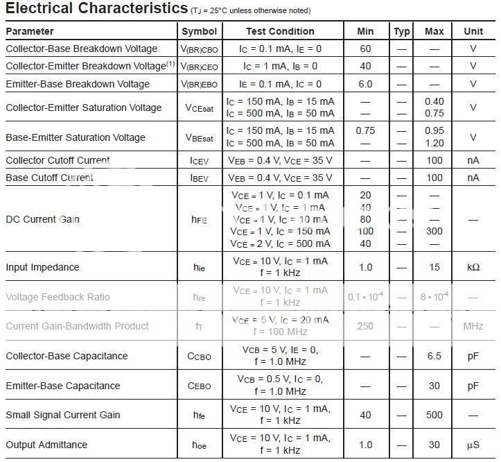
look at the curves of Ic vs Vbe.
it shows how the Ic changes with changes in Vbe.
the transistor starts to pass current when Vbe~400mV
and works as an amplifier when Vbe~600mV.
You want a switch which is nearer the saturated curves.
Vbe~700mV to 1000mV will push the transistor into saturation. But the gain drops very low when saturated.
If you need 260mA you may need as much as 30mA for Ib.
the 2n4401 may get a bit hot with those Ic & Ib.
What you must not have is a Vbe between 400mV and 700mV for any length of time. This will seriously overheat the transistor.
The 2n4401 will probably do for motors requiring less than 100mA.
Look for a >1A device for your fan.
Thanks for the reply.
The part that im not getting is if the base needs to be at 700mV-1000mV, how do schematics work when they have the transistor base at 5 volts (like from an IC output for example). Also I see(as someone said before) that the max base voltage is 6 volts.
I think its my fault that im not understanding it correctly.
This is the site i first looked at to make the circuit: http://www.kpsec.freeuk.com/trancirc.htm
the section i looked at is "Choosing a suitable NPN transistor"
Actually I was just thinking about it....would this relay, with a properly placed diode, work better/easier for that fan? Im thinking it would.
http://www.radioshack.com/product/index.jsp?productId=2062481
http://www.radioshack.com/product/index.jsp?productId=2062481
- Status
- Not open for further replies.
- Home
- Amplifiers
- Solid State
- Transistor as a Switch, is this correct?