Hi all.
I was experimenting (yet again) with the Allison pair. I started this design not focusing on the allison, but on a simple way to cascode the VAS to make it more linear.
In simulation lots of strange things have sprung up in my experiments. At the beginning I would dismiss these as "simulator trash". But with my experience of the simulator I have come to understand that there is a reason for everything, and usually the simulator is saying something important, even though it is easy to misinterpret the output.
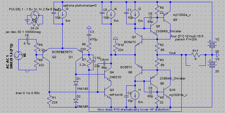
When testing this circuit for distortion, I decided to add R10 to see what would happen. The 1KHz THD did not improve, but the 20KHz THD did by far, and is about 1/3 the 1KHz THD. Something that I don't see often is HF performance better than LF. When I do see it, I make sure to figure out exactly why it happened that way.
This is an interesting case. In this case, increasing Cdom actually decreases HF distortion. Here are the observations:
1: Decreasing C8 and C9 increases THD20.
2: Increasing Cdom will decrease THD20 only until you go above 86p.
3: Replacing D1 and D2 with a constant voltage source does not affect THD.
4: THD vs freq becomes normal with the deletion of R10. (normal constitutes no negative correlation of THD with increasing frequency.)
5: THD20 shows dominant 3rd harmonics, whereas 1KHz THD is 2nd harmonic dominant with the other harmonics following in a roughly downward line.
THD @ 1KHz = .00088%
THD @ 20KHz = .00027%
Maximum load capacitance is 2nF.
Gain is 10.
Here is the schematic:

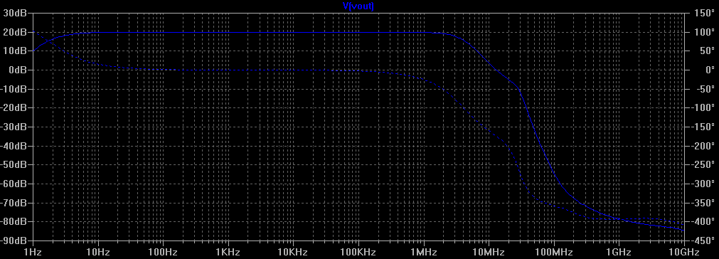
And here is the frequency response:

I have the LTSpice .asc file attached. The 2Sx/MJL output device model are included in the file for your convenience, the rest should be default LTSpice models.
I am fairly sure that the answer lies in the interaction between Cdom, C8 and C9.
If the answer is that R10 makes the VAS current more linear, then why is it only affective at high frequencies?
Thank you for your time,
- keantoken
I was experimenting (yet again) with the Allison pair. I started this design not focusing on the allison, but on a simple way to cascode the VAS to make it more linear.
In simulation lots of strange things have sprung up in my experiments. At the beginning I would dismiss these as "simulator trash". But with my experience of the simulator I have come to understand that there is a reason for everything, and usually the simulator is saying something important, even though it is easy to misinterpret the output.
When testing this circuit for distortion, I decided to add R10 to see what would happen. The 1KHz THD did not improve, but the 20KHz THD did by far, and is about 1/3 the 1KHz THD. Something that I don't see often is HF performance better than LF. When I do see it, I make sure to figure out exactly why it happened that way.
This is an interesting case. In this case, increasing Cdom actually decreases HF distortion. Here are the observations:
1: Decreasing C8 and C9 increases THD20.
2: Increasing Cdom will decrease THD20 only until you go above 86p.
3: Replacing D1 and D2 with a constant voltage source does not affect THD.
4: THD vs freq becomes normal with the deletion of R10. (normal constitutes no negative correlation of THD with increasing frequency.)
5: THD20 shows dominant 3rd harmonics, whereas 1KHz THD is 2nd harmonic dominant with the other harmonics following in a roughly downward line.
THD @ 1KHz = .00088%
THD @ 20KHz = .00027%
Maximum load capacitance is 2nF.
Gain is 10.
Here is the schematic:

And here is the frequency response:

I have the LTSpice .asc file attached. The 2Sx/MJL output device model are included in the file for your convenience, the rest should be default LTSpice models.
I am fairly sure that the answer lies in the interaction between Cdom, C8 and C9.
If the answer is that R10 makes the VAS current more linear, then why is it only affective at high frequencies?
Thank you for your time,
- keantoken
Attachments
The effect of Cdom is expected - it's just the trade between linearity of the VAS and open-loop gain.
I wouldn't expect the bias voltage for the cascode to have much effect simply because the VAS doesn't usually benefit from cascoding much, so it doesn't matter if the cascode is perfect or not.
A resistor to ground from the output of the VAS usually increases distortion (some people do this deliberately) by needlessly throwing away gain, but I have seen cases like yours where it actually improves distortion (2nd harmonic specifically, which is what the VAS produces in the first place). Here's an experiment for you: Measure the open-loop gain at various DC output voltages. My guess is that the gain of the VAS changes with output voltage and the resistor to ground flattens that out.
Mr Evil said:The effect of Cdom is expected - it's just the trade between linearity of the VAS and open-loop gain.
I wouldn't expect the bias voltage for the cascode to have much effect simply because the VAS doesn't usually benefit from cascoding much, so it doesn't matter if the cascode is perfect or not.
A resistor to ground from the output of the VAS usually increases distortion (some people do this deliberately) by needlessly throwing away gain, but I have seen cases like yours where it actually improves distortion (2nd harmonic specifically, which is what the VAS produces in the first place). Here's an experiment for you: Measure the open-loop gain at various DC output voltages. My guess is that the gain of the VAS changes with output voltage and the resistor to ground flattens that out.
You are right that using a better voltage source won't improve the cascode much. I was simply trying to see if the cascode was a factor in our strange phenomenon.
The gain of the VAS changes by 40 from peak to peak (is fairly constant at 1.2k) at 20KHz. Without cascoding, it changes by 3.8K at the same output power and frequency (goes from 0.9k to 4.7k). I would say that cascoding has an enormous affect on VAS performance!!! In my experience on the simulator I have had more luck producing well-behaved amplifiers using a cascoded singleton VAS than I have using a darlington or CFP. It just seems that a single transistor VAS is more stable, and there is less need for a large Cdom (which, except in special cases, increases HF distortion) to make it so.
If your amplifier has .01% THD, it probably won't matter much (unless the VAS is most of your problem). But if you are getting to levels like those of this circuit, it matters quite a bit. I think you should run the circuit in the sim and look at the affect of cascoding on the VAS and THD.
I have begun to use it regularly in my circuits, and it's fairly simple to implement. The VAS will also run cooler, improving the temperature balance of the LTP.
I think you are partially right in that the gain changes at different output powers, because the input impedance of the Allison has a strong 3rd harmonic. But I don't know if this is enough to cause the strangeness here. The open-loop gain stays at 33.6k pretty constantly.
Here is another thing to note:
The best value for Cdom, if we go by THD, is about C8+C9. This means also that the best value of Cdom will pass the same amount of current as C8 and C9 combined. Any thoughts on this? My thoughts are that the capacitor currents at all parts result in a cancellation of device currents, reducing gain. What if the current in Cdom somehow compensates for the current in C8 and C9?
I think this will be very enlightening when we find the answer.
All comments welcome,
- keantoken
You are not the only person to report an improvement in THD by loading the VAS resistively (R10 in your case). I may have to be corrected, but Pavel has also made this comment. However, quite a few practitioners claim it makes no difference or is a waste of loop gain at lower frequencies. Most people who load the VAS resistively do it to get 'wider open loop bandwidth' at the expense of lower loop gain at lower frequencies.
I have simulated this, but on a fully balanced design (+-35V rails and 2 x 22k to ground from each side of the Vbe multiplier. What I found was that without the resistors, the current waveform in the VAS emitter resistors was quite distorted and after I added the resistors, this waveform cleaned up dramatically and in fact was almost a perfect sinusoid (I run the VAS at 27mA). Let me add, that the waveform on the 27mA VAS current standing current that I was looking at was about 500uA - so about 2%.
The overall distortion improvement was not that great at 20KHz - from about .06% to about .04% after I added the resistors.
Could you attach your .asc file? I'm not sure what you are talking about and you refer to emitter resistor in the VAS, where there are none in my schematic.
Also, try making those 22k resistor 47k. Going lower than 22k net impedance increases distortion dramatically.
- keantoken
Also, try making those 22k resistor 47k. Going lower than 22k net impedance increases distortion dramatically.
- keantoken
I might be wrong but D1, D2 should not be in the current mirror. The base of Q4 should be a constant V, the voltage across D1,D2 varies with the mirrror current, (and it varies non linearly). They might be adding feedback?
To get a better idea what R10 is doing try a loopgain plot with and without it (and try 10k 40k) (f you dont know how check the last few pages of the Spice thread) This R will change the VAS gain but it will probably also effect the pole caused by Cdom, (and maybee the pole of the driver stage Alison new to me, Common base driver with local feedback??)
To get a better idea what R10 is doing try a loopgain plot with and without it (and try 10k 40k) (f you dont know how check the last few pages of the Spice thread) This R will change the VAS gain but it will probably also effect the pole caused by Cdom, (and maybee the pole of the driver stage Alison new to me, Common base driver with local feedback??)
Ok, if cascoding works for you then I believe you! I don't usually see it making any difference because Cdom negates the improved bandwidth. Perhaps it's because of the way you have it connected, both sides of the LTP see a more equal load? Try moving the cascode bias voltage out of the LTP and see if it makes things worse.
It might also be interesting to try replacing R10 with a resistor from VAS output to the inverting input, sized to give the same open-loop gain.
It might also be interesting to try replacing R10 with a resistor from VAS output to the inverting input, sized to give the same open-loop gain.
Rafael.luc said:Hi keantoken
Tested in the square wave?
That peak below 0dB, can be oscillation...
The miller cap in the feedback network makes for perfect square response. I haven't seen any oscillation here unless I put more than 2nF across the load.
blueskynis said:I saw schematics with a capacitor of about 1u in series with the resistor to not load the VAS at lower frequencies. Maybe you also should try it to improve lower frequencies THD.
The resistor doesn't have a significant affect on distortion at low frequencies, if I recall correctly. You are right and I want THD to be balanced across the spectrum. My reason for this thread is to determine the cause for lower HF THD and be able to rework the circuit to have the same benefit at LF.
Bonsai said:Keantoken,
the circuit I use is a std fully balanced VAS topology - no rocket science there.
Since I run th e VAs at about 25-30mA, driving 10k and higher VAS resistive load to ground is no problem.
I think you're ahead of me here. You say it's not rocket-science but I've never been through an electronics class. So it would go a long ways to help me understand if you would at least draw a rough schematic. I Googled and found some "balanced VAS" schematics but I still don't know exactly what you mean.
cbdb said:I might be wrong but D1, D2 should not be in the current mirror. The base of Q4 should be a constant V, the voltage across D1,D2 varies with the mirrror current, (and it varies non linearly). They might be adding feedback?
To get a better idea what R10 is doing try a loopgain plot with and without it (and try 10k 40k) (f you dont know how check the last few pages of the Spice thread) This R will change the VAS gain but it will probably also effect the pole caused by Cdom, (and maybee the pole of the driver stage Alison new to me, Common base driver with local feedback??)
I replaced the two diodes with a CVS and it did not affect distortion significantly. We could bypass the diodes with a capacitor, but still I did not find a significant effect on distortion. The cascode voltage is already fairly constant, if you compare it to the tremendous voltage variations that would be on the VAS were it not there.
Mr Evil said:Ok, if cascoding works for you then I believe you! I don't usually see it making any difference because Cdom negates the improved bandwidth. Perhaps it's because of the way you have it connected, both sides of the LTP see a more equal load? Try moving the cascode bias voltage out of the LTP and see if it makes things worse.
It might also be interesting to try replacing R10 with a resistor from VAS output to the inverting input, sized to give the same open-loop gain.
I am very sorry if I'm being difficult. As far as the LTP seeing an equal load, I'm not sure, but I would think this would only matter when we take into account the Cbc of the LTP transistors. Still, sometimes it does matter, just not here. In simulation I found that a good way to increase stability was to add a resistor right on the collector of Q2. I don't think Cdom negates the improved bandwidth, because we don't need to change the value of Cdom when the cascode is added: cascoding adds and doesn't take away. If you run the simulation you will see that cascoding improves the HF THD significantly if you take it out and don't change Cdom. Trading the two diodes for a voltage source is equivalent to removing the cascode reference from the LTP, because a perfect source isolates all the LTP current. So no, the current interaction between the LTP and cascode don't affect performance, but for good measure I should probably bypass the diodes with a cap so as to isolate any transients.
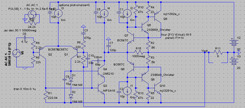
Okay, Here is the schematic Version 2:

The HF phenomenon still applies, only C8 and C9, and R10 have switched places. R10 was split into R10 and R13, and C8 and C9 were joined to form C7. I think I prefer the caps to be on the CFPs however, which improves Allison stability.
Distortion specs are almost the same:
THD @ 1KHz = .00088%
THD @ 20KHz = .00037%
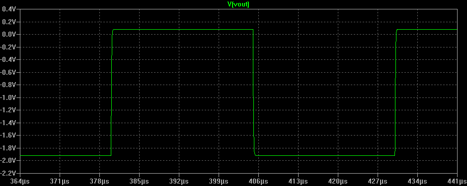
Here is a square wave.

The frequency response is pretty much the same...
I still think the key is in that the current through C7 and and Cdom are in phase with each other, and out of phase with output voltage.
Thank you for your time,
- keantoken
keantoken said:
The miller cap in the feedback network makes for perfect square response. I haven't seen any oscillation here unless I put more than 2nF across the load.
I test with 330nF, 2nF seems little...
I believe that it should degenerate the differential pair slightly, in its circuit, differential pair must be saturated with ~50mV.
Another thing to evaluate the distortion in accordance with negative feedback that is using, each modification should see their open loop
Bonsai said:
The overall distortion improvement was not that great at 20KHz - from about .06% to about .04% after I added the resistors.
I also use resistance shunt, if you look in the book Dr.Self , will notice that the distortion is very small loading VAS (0,01%), in a circuit with negative feedback is very little to difference.
keantoken said:
The miller cap in the feedback network makes for perfect square response. I haven't seen any oscillation here unless I put more than 2nF across the load.
The resistor doesn't have a significant affect on distortion at low frequencies, if I recall correctly. You are right and I want THD to be balanced across the spectrum. My reason for this thread is to determine the cause for lower HF THD and be able to rework the circuit to have the same benefit at LF.
I think you're ahead of me here. You say it's not rocket-science but I've never been through an electronics class. So it would go a long ways to help me understand if you would at least draw a rough schematic. I Googled and found some "balanced VAS" schematics but I still don't know exactly what you mean.
I replaced the two diodes with a CVS and it did not affect distortion significantly. We could bypass the diodes with a capacitor, but still I did not find a significant effect on distortion. The cascode voltage is already fairly constant, if you compare it to the tremendous voltage variations that would be on the VAS were it not there.
I am very sorry if I'm being difficult. As far as the LTP seeing an equal load, I'm not sure, but I would think this would only matter when we take into account the Cbc of the LTP transistors. Still, sometimes it does matter, just not here. In simulation I found that a good way to increase stability was to add a resistor right on the collector of Q2. I don't think Cdom negates the improved bandwidth, because we don't need to change the value of Cdom when the cascode is added: cascoding adds and doesn't take away. If you run the simulation you will see that cascoding improves the HF THD significantly if you take it out and don't change Cdom. Trading the two diodes for a voltage source is equivalent to removing the cascode reference from the LTP, because a perfect source isolates all the LTP current. So no, the current interaction between the LTP and cascode don't affect performance, but for good measure I should probably bypass the diodes with a cap so as to isolate any transients.
Okay, Here is the schematic Version 2:
http://i198.photobucket.com/albums/aa290/keantoken/AllisonQuestionmark_2.gif
The HF phenomenon still applies, only C8 and C9, and R10 have switched places. R10 was split into R10 and R13, and C8 and C9 were joined to form C7. I think I prefer the caps to be on the CFPs however, which improves Allison stability.
Distortion specs are almost the same:
THD @ 1KHz = .00088%
THD @ 20KHz = .00037%
Here is a square wave.
http://i198.photobucket.com/albums/aa290/keantoken/AllisonQuestionmark_2_Square.gif
The frequency response is pretty much the same...
I still think the key is in that the current through C7 and and Cdom are in phase with each other, and out of phase with output voltage.
Thank you for your time,
- keantoken
that squarewave is just beautiful
Not many amplifiers can show such .. at least not when built.
I would be very pleased to see such wave in my Simulator.
Because if, then I know that my Amplifier circuit
have good potential to be real good in reality.
Keep up your good work, keantoken.
I know how good you are. unique ideas and all
andt this .. while you are still in learning-developing sklills phase.
What may b'come from out of your head later .. we never know.
Regards
lineup
I replaced the two diodes with a CVS
If the CVS was in the LTP then it might affect the LTP performance.
We could bypass the diodes with a capacitor
Putting the cap in the LTP loads it down at higher freqs. Cant you just move the diodes/cap out of the LTP and feed it with a resistor? This would make it look like a more standard design.
If the CVS was in the LTP then it might affect the LTP performance.
Never mind. It shouldnt matter.
cbdb said:
If the CVS was in the LTP then it might affect the LTP performance.
Putting the cap in the LTP loads it down at higher freqs. Cant you just move the diodes/cap out of the LTP and feed it with a resistor? This would make it look like a more standard design.
If I use a large value cap the loading should be the same across most of the audio spectrum. In any case, the unused leg of the LTP usually has no load between it and ground.
I don't like your comment about "making it look more normal". Unless we are all trying to design the same amp, what is the use of having a standard when it comes to topology? It's like religious categories... I don't fit into any of them...
I think this idea of making a circuit look more "standard" only causes people to get ignored when they come along with a good and unique idea.
cbdb said:
Never mind. It shouldnt matter.
All things matter. I enjoyed replying to your post.
- keantoken
- Status
- This old topic is closed. If you want to reopen this topic, contact a moderator using the "Report Post" button.
- Home
- Amplifiers
- Solid State
- Can someone tell me how this works?