I came across this at work. Although Wenzel make microwave components, they face the same issues with voltage regulators that audiophiles do.
Their 'finesse' circuit is a simple way of reducing the noise (ie non-DC) output of voltage regulators.
http://www.wenzel.com/documents/finesse.html
The only down-side is that you'll need a spectrum analyser if you want to tune the circuit to maximise noise reduction. It should still be possible to achieve 20-30dB of noise suppression using only 1% tolerance resistors.
Sud
Thanks for this link Sud
The ideas and circuits presented by this link will be very useful in reducing power supply noise to a minimum.
I don't believe that the "noise shunt" term that they use is correct since the circuit amplifies the AC noise component coming out of a voltage regulator and then feeds it back out of phase on the other side of a dropping resistor that is in series with the load. Thus it is more of a noise nulling circuit rather than a shunt. The gain of the amplifier stage could be made adjustable and thus adjusted with a small trim pot for maximum nulling effect.
The draw back of the circuit is that any capacitors on the output end of the series resistor to ground will cause problems and reduce the effectiveness of the circuit. Even if fairly small values of capacitors are used. If such a capacitor is large enough the circuit will have no or a extremely limited effect on noise reduction. There would certainly be less noise reduction toward the higher frequency end of the spectrum.
This is actually quite a good way to reduce noise over a fairly high bandwidth from a regulated power supply. Especially if there is no need for further filter capacitors to be wired directly to the power filter output and the load is more or less constant.
When I have a chance I will play with the concept provided by the link and make some measurements. This may be some what difficult since I don't have access to a screen room at the present time to help keep external noise away.
Good link, great idea.
John Fassotte
Alaskan Audio
[Edited by alaskanaudio on 12-12-2001 at 06:16 AM]
Good info! This reminds me of another link at the maxim site:
http://dbserv.maxim-ic.com/appnotes.cfm?appnote_number=169
Seems to used similar concept.
Michael
http://dbserv.maxim-ic.com/appnotes.cfm?appnote_number=169
Seems to used similar concept.
Michael
Finnesse regulator noise
Hi everyone,
I built this circuit some time back, and it does work, although emitter resistor value, in the transistor circuits, is critical for best performance.
I have some SPICE plots somewhere if anyone is interested.
I didn't like it's sound though, powering various bits of a Naim 42 preamp, but that could have been due to inadequate transistor performance (fT). Bit if a 'bun-fight' between filter and circuit possibly.
I've just built a 4 transistor discrete regulator, based on the Walt Jung POOGE series that appeared in 'The Audio Amateur'.
I've made a simple mod that offers stunning noise performance when compared with any monolithic regulator, whilst lowering output impedance and improving line rejection dramatically.
Again, if interested I'll post circuit / results.
Andy.
By (very) popular demand
POOGE 5.51 updated.
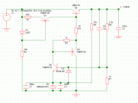
Here's the schematic for the regulator, based upon the design that appeared in 'The Audio Amateur'.
My version uses different compnents (surface mount) and makes a simple, but very major improvement. The AC gain of the feedback path is reduced to unity, preventing the circuit from amplifying the reference noise (which is actually an LM329 sub-surface zener diode which has the least self-generated noise I know of).
This also reduces output impedance from a nominal 2mOhm (ruler flat to 200kHz!) to about 0.2mOhm. Line rejection can be as high as 100dB (again virtually ruler flat, unlike LM317 / LT1086 et al, which give about 80dB below 1kHz).
It's not possible to reduce LF noise further since it requires brute force filtering (caps across the reference) amd is only effective when the capacitor impedance becomes smaller than the reference impedance.
C4 is the magic component, see next post for actual spectrum analyser plots of noise, compared to other PSU's.
Andy.
Attachments
And now for the results
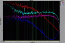
Here's the FFT plots, taken using constant bandwidth scalings (not octave scalings).
The Red trace is the discrete regulator noise without C4.
Light blue is a well known audio manufacturers entry level PSU, based on LM317 regulators.
Pink is a PSU based upon an LT1086 with LM329 external reference.
Dark blue is the regulator above.
Scaling is accurate in realtive terms, but not calibrated absolutely.
It's actually quieter than a battery when drawing current, the chemical reaction that goes on within a cell produces nasty, non-correlated random noise when actually working. And batteries have higher impedance!
P.S. The rise in noise at 20kHz is the PC sound card, not the regulator. There is a low noise 30dB buffer amp to increase PSU noise above the measurement noise floor of the soundcard, but the POOGE reg drops below this - I need to build a higher gain buffer!
Attachments
Re: A question
A question: what look to be 10dB spikes at 50, 100Hz or thereabouts...are those the results of the soundcard.
Grataku,
The 50Hz is a result of inadequate screening of the measurement leads and can be eliminated easily by better screening and balanced inputs to the buffer amplifier.
The other mains harmonics (UK mains = 50Hz) are a result of less than perfect Kelvin sensing.
When measuring, or connecting these regulators to any circuit it is important that the circuit being powered is connected directly to the regulator sense points, particularly the -ve Kelvin sense point.
Failure to do this in a mains-powered supply will give rise to mains harmonic content from the sudden peak currents flowing in the PSU earth. Big smoothing capacitors can actually make things worse as the reduced conduction angle of the diodes results in some nasty peak currents.
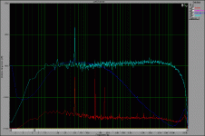
Attached is another plot of an LT1086 / LM329 based PSU (light blue plot), POOGE reg (dark blue) and a Sulzer-based regulator made with a TL071 I had kicking around in my parts bin.
The Sulzer reg is again imperfect - veroboard isn't very conducive to proper circuit layout.
The noise of the Sulzer cicruit wil be lower if an op-amp with lower voltage noise is used, The TL071 is't very quiet at about 18nV/root Hz.
Sulzer used an NE5534, which has a 4nV/root Hz volotage noise figure. Better choices may exist but I want to use something that's cost effective as it allows one to litter them freely around a circuit without the cost being prohibitive.
I'm going to design a PCB for the Sulzer reg, as it can be made much more cheaply than the Jung / Didden regs (less than the cost of the AD797 used in the Jung / Didden!), and the capacitor values are lower, keeping size down. The intention is to make a drop-in replacment for any 3-terminal reg, bu configuring the PCB pinout with links.
The Jung / Didden reg's are awesome, but one pays a high price for what is, relative to the Sulzer circuit, only a small improvement in many areas. The Sulzer circuit is dramatically better than any 3-terminal reg.
Andy.
Attachments
Where are all the schematics you are referring to, Andy ? Did I miss another thread ?
I must admit that I have difficulties with SMD layouts in terms of DIY (to Do It Myself, actually). Do you think it is possible to create this PSU to the same specs with "normal" components ?
Do you think that a combination of BD135 / ZTX 653 / ZTX 753 / hi-q zener would work ? How critical is the value of C3 (820n) ? Is D1 a red LED ?
I suppose the values in your schematic are for a 24V output.
best greetings
Klaus
ps: I just returned from a longer project in Zimbabwe ...
Klaus.
I'm just about to start the layout, with through-hole components, of a Low Drop-Out, less than 0,5V, low current, I<400mA, low noise regulator with BD135/136 as series-elements.
I'm to use it in my preamp, as well as my RIAA.
If anyone's interested, I can post the schematic as well as the PCB-layout as soon as I'm done.
Sulzer Schematic
Klaus,
The Sulzer reg was built using conventional components on veroboard, I only used SM for the POOGE circuit.
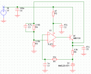
Here's the schematic for those wishing to try it, the Zener is the ubiquitous LM329, use tantalum caps or, for the 1uF reference filter, a 1uF film capacitor.
Use an NE5534 or similar low voltage noise op-amp, I only used a TL071 because I had one lying around, they are noisier though!
Andy.
P.S. Values shown are for a nominal 15V, just change the divider ratio to change, keeping the impedances on each op-amp input equal for best DC stability with temperature.
Attachments
- Status
- This old topic is closed. If you want to reopen this topic, contact a moderator using the "Report Post" button.
- Home
- Amplifiers
- Solid State
- Reducing noise in voltage regulators


