JC expressed some concerns regarding the HPS 3.0 ultra low noise MM stage functionality and differences to his Vendetta low noise MM stage.
Well, I'm not retired and I certainly can't afford to put together a throughout analysis, so I will only quickly enumerate and address them, according to my understanding:
a) "Our only difference is the effective source resistance."
b) "For precision ultra low frequency designs, and even DC coupling, we use Toshiba 2SK389, pre sorted for Idss and DC offset. Then pairs of 2SK389's are paralleled together, even multiple pairs would work, to subtract offset. Less than 100uV of DC offset is possible".
c) "Now, how do we make ELEGANT input circuits that have other qualities, such as inherent balance, and DC optimization, without losing the noise characteristics?"
d) "Certainly no feedback loop can be conveniently used."
e) "Paralleling fets endlessly can produce a very low noise input stage, but it lacks everything else. For example, how do you couple to the next stage?"
f) "There is no inherent DC stability or even order distortion reduction. It would appear that negative feedback is nearly impossible, without effectively shorting the input,(not always the best effective load), so watch out for CCIR IM distortion due to the RIAA network amplifying the inherent distortion of this stage out of line from typical expectations."
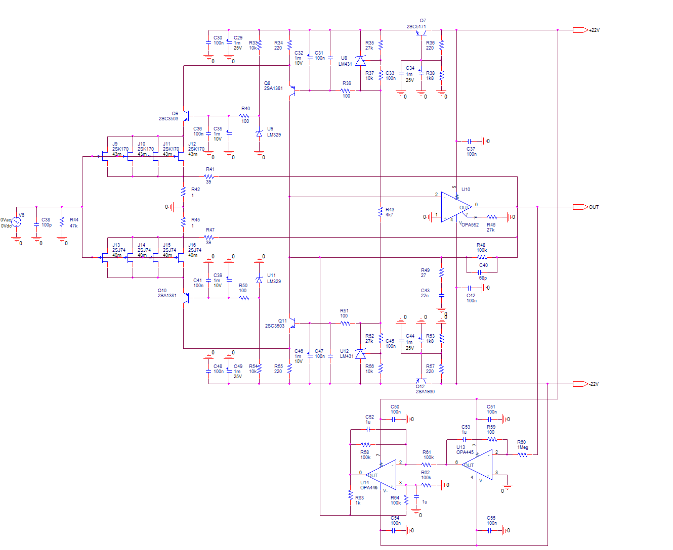
The latest HPS3.0 input stage schematic is attached. It keeps the same gain of 40, noise of about 0.32nV/rtHz and 46dB headroom over the entire audio spectrum. It uses a high voltage/high current JFET input opamp OPA552. For those not having access to such, a combination of any JFET input opamp and high current buffer (LT1010, LME49600, etc...) can be used with equivalent results.
Let's analyze John's comments one by one:
a) It is not. According to my experience, paralleling more than 5 2SK170 renders a barely stable input stage. The HPS3.0 arrangement allows paralleling 8 complementary devices, while keeping an excellent stability. I have tried up to 16 devices for 0.25nV/rtHz noise, without any significant stability problems.
Another significant difference is the noise independence on the JFET load R34/R55. The stage open loop gain does not depend on these and their noise contribution is negligible over a wide range of values. The open loop gain of the entire amp is about gm*R16 where gm is the JFET input stage transconductance; for a bias point of about 8mA, the open loop gain is araound 82dB, rendering a LF loop gain of 55dB. The R34/R55 noise rejection is over 50dB.
b) Can't make it more precision than this one, allowing DC coupling with an output offset of 100uV over a wide range of JFET Idss. In fact, this arrangement makes JFET matching absolutely useless; any JFETs in the same (BL, V) class can be used, the servo is taking care of balancing the output. Scott and others (including myself) already showed that JFET matching does nothing for decreasing the noise, therefore the noise performance is exactly the same as with handmatched JFETs (a JC trademark). The current based servo deserves some discussion, see below.
c) This is as elegant as it can be. Again, it's DC balanced and has a few unique features. First, it's almost entirely current based (rather than voltage). I already showed that the open loop gain does not depend on the JFET load (and so is noise). In fact, any noise voltage at the U3 inverting input (including the opamp input voltage noise) has no impact on the output noise (because the very low impedance at this node). OTOH, the R16 noise is divided by the opamp open loop gain, being in fact negligible as well (less than 1ohm equivalent resistence). What's left to contribute to the noise are 1) The opamp input current noise, mitigated by using a JFET input opamp 2) the cascode transistors current noise, mitigated by using very low noise bipolars, and that's anyway contributing with the ponder as gm*Ui that is about 160mA/V*0.5mV=80uA. and finally 3) the servo output current noise.
The servo imposes some challenges. First, it has to have a large gain transconductance amp. Second, it has to have very low output current noise, because this adds directly to the output voltage noise through R16. It also has to have a decent dynamic range, so that the output can accomodate rather large input JFET current mismatches.
To achieve these, again a couple of high voltage JFET input opamp are used. Again, the voltage noise is not critical here; while the first servo stage noise is filtered by the integrator cap, the voltage to current convertor gain of about 1mA/V is still very low noise, simply because the input current noise of the JFET opamp is very small. The 100kohm resistor noise is filtered by the 1uF caps.
d) And here's an example on how feedback can be used, to reduce distortions. There's about 23dB of loop gain allowing that. The OPA552 opamp has 200mA output current, allowing a 4V output before clipping.This accounts for a max input of 100mV, or about 46dB headroom. Is this good enough?
e) Here's an example: the servo allows DC coupling to the output.
f) The feedback loop is taking care of reducing distortion much more effective than any device hand matching can do. Yes, feedback is possible as you can see.
Bottom line, 0.31nV/rtHz noise both measured and simulated, 25% less than the best case Vendetta, measured 0.005% THD 20-20KHz, measured 0.005% IMD 19+20KHz, allows DC coupling to the output, 46dB headroom, no JFET matching or sorting required to achieve all these, and... sounds good") (according to my observations and a few other guys that already buit this) Use it with the RIAA correction/gain stage of your choice. Can go down to 0.25nV/rtHz with sorted JFETs...
(according to my observations and a few other guys that already buit this) Use it with the RIAA correction/gain stage of your choice. Can go down to 0.25nV/rtHz with sorted JFETs...
Beat this! A bipolar version to follow...
EDIT: There's a 1uF cap in parallel to R62, sorry for the error.
Well, I'm not retired and I certainly can't afford to put together a throughout analysis, so I will only quickly enumerate and address them, according to my understanding:
a) "Our only difference is the effective source resistance."
b) "For precision ultra low frequency designs, and even DC coupling, we use Toshiba 2SK389, pre sorted for Idss and DC offset. Then pairs of 2SK389's are paralleled together, even multiple pairs would work, to subtract offset. Less than 100uV of DC offset is possible".
c) "Now, how do we make ELEGANT input circuits that have other qualities, such as inherent balance, and DC optimization, without losing the noise characteristics?"
d) "Certainly no feedback loop can be conveniently used."
e) "Paralleling fets endlessly can produce a very low noise input stage, but it lacks everything else. For example, how do you couple to the next stage?"
f) "There is no inherent DC stability or even order distortion reduction. It would appear that negative feedback is nearly impossible, without effectively shorting the input,(not always the best effective load), so watch out for CCIR IM distortion due to the RIAA network amplifying the inherent distortion of this stage out of line from typical expectations."
The latest HPS3.0 input stage schematic is attached. It keeps the same gain of 40, noise of about 0.32nV/rtHz and 46dB headroom over the entire audio spectrum. It uses a high voltage/high current JFET input opamp OPA552. For those not having access to such, a combination of any JFET input opamp and high current buffer (LT1010, LME49600, etc...) can be used with equivalent results.
Let's analyze John's comments one by one:
a) It is not. According to my experience, paralleling more than 5 2SK170 renders a barely stable input stage. The HPS3.0 arrangement allows paralleling 8 complementary devices, while keeping an excellent stability. I have tried up to 16 devices for 0.25nV/rtHz noise, without any significant stability problems.
Another significant difference is the noise independence on the JFET load R34/R55. The stage open loop gain does not depend on these and their noise contribution is negligible over a wide range of values. The open loop gain of the entire amp is about gm*R16 where gm is the JFET input stage transconductance; for a bias point of about 8mA, the open loop gain is araound 82dB, rendering a LF loop gain of 55dB. The R34/R55 noise rejection is over 50dB.
b) Can't make it more precision than this one, allowing DC coupling with an output offset of 100uV over a wide range of JFET Idss. In fact, this arrangement makes JFET matching absolutely useless; any JFETs in the same (BL, V) class can be used, the servo is taking care of balancing the output. Scott and others (including myself) already showed that JFET matching does nothing for decreasing the noise, therefore the noise performance is exactly the same as with handmatched JFETs (a JC trademark). The current based servo deserves some discussion, see below.
c) This is as elegant as it can be. Again, it's DC balanced and has a few unique features. First, it's almost entirely current based (rather than voltage). I already showed that the open loop gain does not depend on the JFET load (and so is noise). In fact, any noise voltage at the U3 inverting input (including the opamp input voltage noise) has no impact on the output noise (because the very low impedance at this node). OTOH, the R16 noise is divided by the opamp open loop gain, being in fact negligible as well (less than 1ohm equivalent resistence). What's left to contribute to the noise are 1) The opamp input current noise, mitigated by using a JFET input opamp 2) the cascode transistors current noise, mitigated by using very low noise bipolars, and that's anyway contributing with the ponder as gm*Ui that is about 160mA/V*0.5mV=80uA. and finally 3) the servo output current noise.
The servo imposes some challenges. First, it has to have a large gain transconductance amp. Second, it has to have very low output current noise, because this adds directly to the output voltage noise through R16. It also has to have a decent dynamic range, so that the output can accomodate rather large input JFET current mismatches.
To achieve these, again a couple of high voltage JFET input opamp are used. Again, the voltage noise is not critical here; while the first servo stage noise is filtered by the integrator cap, the voltage to current convertor gain of about 1mA/V is still very low noise, simply because the input current noise of the JFET opamp is very small. The 100kohm resistor noise is filtered by the 1uF caps.
d) And here's an example on how feedback can be used, to reduce distortions. There's about 23dB of loop gain allowing that. The OPA552 opamp has 200mA output current, allowing a 4V output before clipping.This accounts for a max input of 100mV, or about 46dB headroom. Is this good enough?
e) Here's an example: the servo allows DC coupling to the output.
f) The feedback loop is taking care of reducing distortion much more effective than any device hand matching can do. Yes, feedback is possible as you can see.
Bottom line, 0.31nV/rtHz noise both measured and simulated, 25% less than the best case Vendetta, measured 0.005% THD 20-20KHz, measured 0.005% IMD 19+20KHz, allows DC coupling to the output, 46dB headroom, no JFET matching or sorting required to achieve all these, and... sounds good
(according to my observations and a few other guys that already buit this) Use it with the RIAA correction/gain stage of your choice. Can go down to 0.25nV/rtHz with sorted JFETs...Beat this! A bipolar version to follow...
EDIT: There's a 1uF cap in parallel to R62, sorry for the error.
To me, this looks like an engineering solution to a problem that doesn't exist.
1/ No vinyl record has a noise floor low enough to need quad'ed 2SK's & 2SJ's, that would be more than quiet enought for any MC cart, let alone a MM. We have never had a noise problem with just one 2SK in a direct in MC stage...
2/ The front end is super quiet for sure, but why destroy the sound of the thing by adding ~128dB of slowish opamp OLG after the discretes? That must equate to something like 90dB of global NFB - maybe more.
Have you listened to it?
Regards, Allen (Vacuum State)
Wavebourn said:Seeing this I imagine a ribbon microphone.
Me too, the extreme version is definately not overkill for a transformerless ribbon mic (rs = milli-Ohm). I think only the most low output Ortophon MC etc. benefits from .25nV of noise.
Allen Wright said:To me, this looks like an engineering solution to a problem that doesn't exist.
1/ No vinyl record has a noise floor low enough to need quad'ed 2SK's & 2SJ's, that would be more than quiet enought for any MC cart, let alone a MM. We have never had a noise problem with just one 2SK in a direct in MC stage...
2/ The front end is super quiet for sure, but why destroy the sound of the thing by adding ~128dB of slowish opamp OLG after the discretes? That must equate to something like 90dB of global NFB - maybe more.
Have you listened to it?
Regards, Allen (Vacuum State)
1) Well, I use this at a total gain of 1000 (@1KHz) with a 0.2mV cartridge. To put 100W into the load, a total gain of about 1000*5*28=140,000 is required. 0.4nV/rtHz means about 60nV 20-20KHz or an output of about 10mV in the speakers. I can clearly hear the hiss in my 96dB sensitivity speakers, and I really hate hiss (must be something from the childhood
 ) Hence, I need better than 0.4nV/rtHz. And secondly, its really entertaining to beat JC and his entire GEB with an engineering stick
 2) To be able to apply feedback and bring down the distortions to under what can be achieved by matching devices. No, its not slow at all, slew rate is around 15V/us (if memory serves) and this means a worst case rise/fall time of 250nS. Need better for vinyl?
Yes, according to my own opinion and a few other guys that already built this, it sounds absolutely great.
BTW, the design can be simplified by replacing the voltage references with simple resistive dividers, AC decoupled of course. The current schematic reflects my own preference(s), YMMV.
Syn,
Your opening line talked only about MM:
>>JC expressed some concerns regarding the HPS 3.0 ultra low noise MM stage functionality and differences to his Vendetta low noise MM stage.<<
That's what I was basing my comments on. Using it with a low output MC makes much more sense - except for the opamp...
Is the hiss worse than vinyl noise?
Regards, Allen (Vacuum State)
Allen Wright said:Syn,
Your opening line talked only about MM:
>>JC expressed some concerns regarding the HPS 3.0 ultra low noise MM stage functionality and differences to his Vendetta low noise MM stage.<<
That's what I was basing my comments on. Using it with a low output MC makes much more sense - except for the opamp...
Is the hiss worse than vinyl noise?
Regards, Allen (Vacuum State)
Sorry, obviously a typo
Of course, for MM 1nV/rtHz (that is, one JFET) is anything that is really required.No, the vinyl hiss is higher.
scott wurcer said:
Me too, the extreme version is definately not overkill for a transformerless ribbon mic (rs = milli-Ohm).
Probably, smaller and cheaper transformer would be needed. Anyway, it is a great thing, though may be simplified without loss of functionality, and I like current to voltage conversion he used.
In the photos of earlier versions of this preamp, there's a pre-packaged line filter at the AC mains input.
Have you found the capacitive coupling of the AC mains to the chassis to be a problem? Since you've clearly given a lot of thought to the entire design, how did you get around this common problem?
For people not familiar with this challenge, Bill Whitlock of Jensen Transformers has written a lot about subject. Here's a less technical article:
http://digitalcontentproducer.com/mag/avinstall_noise_annoys/
There's more to found via Google.
courage said:Syn08,
Must be me or my 2 different browsers, but I don't see any attachment. Would you or somebody else care to post it once more or send me a copy by mail?
TIA,
Franklin
It's again the old problem: people using certain ISP's can't access my web site where the picture is hosted.
Send me an email and I'll reply with the schematic.
CG said:In the photos of earlier versions of this preamp, there's a pre-packaged line filter at the AC mains input.
Have you found the capacitive coupling of the AC mains to the chassis to be a problem? Since you've clearly given a lot of thought to the entire design, how did you get around this common problem?
For people not familiar with this challenge, Bill Whitlock of Jensen Transformers has written a lot about subject. Here's a less technical article:
http://digitalcontentproducer.com/mag/avinstall_noise_annoys/
There's more to found via Google.
That was the previous design, using a different topology and noise performance was at 0.6-0.7nV/rtHz. I had no problems, as long as the the power supply is hosted in a different enclosure and I use separate signal and power grounds and ferrites on all cables.
Don't know in this design yet, I just got the final PCB's from www.4pcb.com I'll let you know about the outcome. Currently, this thing is running on an old PCB powered from a HP6627A low noise lab power supply.
originally posted by syn08
I just got the final PCB's from www.4pcb.com I'll let you know about the outcome.
I was just looking at their website and will be interested in your opinion. Did you use their software or another package?
Wavebourn said:
Transformers are your friends. Ask Jensen which to buy and how much to pay.
Ahh, actually that wasn't the question.
SYN08 has responded about his previous design and how that worked. When his new design is complete he will likely report on it as well.
2/ The front end is super quiet for sure, but why destroy the sound of the thing by adding ~128dB of slowish opamp OLG after the discretes? That must equate to something like 90dB of global NFB - maybe more.
Have you listened to it?
This stuff is BS for sure, sort of cross pollution of theads
PH104 said:
I was just looking at their website and will be interested in your opinion. Did you use their software or another package?
I'm using Cadence OrCad/Layout Plus. However, whatever software that can output Gerber and Excellon drill files will do just fine. Their online design check is amazing, it will let you see exactly what they understand from your design.
These guys are great. The only thing killing me (as a Canadian) is shipping and taxes, which are simply outrageous ($75 plus 13% taxes on PCBs cost, for a 10oz. envelope through FedEx). Even so, they are still cheaper than local houses (like www.apcircuits.com in Alberta), at least for large boards.
I could do them in China for cheaper, but shipping is still very expensive, and have to add 5% taxes for merchandise outside North America.
Whatever, I'm not going back to the etch&drill exercise, time is to short and expensive. Perhaps I'll do it after retirement, not anytime soon
- Status
- This old topic is closed. If you want to reopen this topic, contact a moderator using the "Report Post" button.
- Home
- Amplifiers
- Solid State
- Addressing John Curl's concerns on low noise designs