Hi there,
although I browse a lot through this forum and learned quite a bit reading the posts, I never posted very much myself. However, I would like to ask for your opinion of my suggestion of a single-ended tube-Mosfet follower, before I think about transferring it from SPICE into the real world.
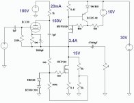
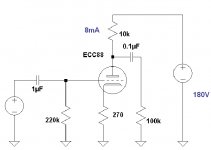
The idea is based on a 2007 publication in the tubecad journal and is based on three components: A triode, a power mosfet and a current source.
The current source is the load for the mosfet and isolates it from the unavoidable ripple of the high current power supply (an idea that Andrea Ciuffoli and Stephen Moore implemented). The voltage for the triode will be smoothed carefully through a C-L-C filter.
The ECC88 and the IRFP240 form a 100% feedback loop. The signal appears at the 1k anode resistor. The ECC88 plate impedance is 2.6k. Hence the impedance to drive the gate plus the Miller capacitance of the IRFP240 is around 720 ohms.
From the drain the signal is fed back into the ECC88 cathode plus it is fed into the output capacitor. The triode is supposed to control the whole circuitry. According to the SPICE simulation the amplifier should be able to deliver 20W into a 4 ohm speaker.
Critical aspects:
The drain follower topology may induce distortion
There is a feedback loop.
Driving the Mosfet with the rather high tube impedance may be critical
There is an electrolyte output capacitor
Any comment is greatly appreciated
Cheers
KlausB
although I browse a lot through this forum and learned quite a bit reading the posts, I never posted very much myself. However, I would like to ask for your opinion of my suggestion of a single-ended tube-Mosfet follower, before I think about transferring it from SPICE into the real world.
The idea is based on a 2007 publication in the tubecad journal and is based on three components: A triode, a power mosfet and a current source.
The current source is the load for the mosfet and isolates it from the unavoidable ripple of the high current power supply (an idea that Andrea Ciuffoli and Stephen Moore implemented). The voltage for the triode will be smoothed carefully through a C-L-C filter.
The ECC88 and the IRFP240 form a 100% feedback loop. The signal appears at the 1k anode resistor. The ECC88 plate impedance is 2.6k. Hence the impedance to drive the gate plus the Miller capacitance of the IRFP240 is around 720 ohms.
From the drain the signal is fed back into the ECC88 cathode plus it is fed into the output capacitor. The triode is supposed to control the whole circuitry. According to the SPICE simulation the amplifier should be able to deliver 20W into a 4 ohm speaker.
Critical aspects:
The drain follower topology may induce distortion
There is a feedback loop.
Driving the Mosfet with the rather high tube impedance may be critical
There is an electrolyte output capacitor
Any comment is greatly appreciated
Cheers
KlausB
Attachments
I see several problems. First the gate voltage needed for that
bottom mosfet will varry from device to device and also on how
hot it gets so it needs to be done with a pot.
Then the current source may have a problem. That 100 ohm
resistor from the 15v supply will let the transistor and diode
pull ~110 ma and I believe that diode is only rated at 100ma
change it to something like 5k. Or better still look at how
Nelson does these 2 things in his ZEN amplifier!
KlausB,
not bad, coming up with something like that right away.
What is the preceding stage?
I don`t find those critical aspects especially bothersome (OK, some elaboration would be needed here).
Crss=160pF
Ciss=1275pF
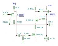
I would try to modify it in this manner:
not bad, coming up with something like that right away.
What is the preceding stage?
I don`t find those critical aspects especially bothersome (OK, some elaboration would be needed here).
Crss=160pF
Ciss=1275pF
I would try to modify it in this manner:
Attachments
Lumba, in the circuite you posted you left out a voltage source
for the irf240 to set it's drain at 15v. Without this the device is
100% off.
But back to the first circuite what advantage does this have over
a standard mosfet power follower other than higher input impedience?
for the irf240 to set it's drain at 15v. Without this the device is
100% off.
But back to the first circuite what advantage does this have over
a standard mosfet power follower other than higher input impedience?
woody said:
But back to the first circuite what advantage does this have over
a standard mosfet power follower other than higher input impedience?
Now it is voltage controlled instead of charge controlled. Still, I would add a resistive divider in the feedback loop. Just my humble opinion.
Wavebourn,
It can be done, however, in this mode, using 100% feedback, it is a voltage follower, just in case someone is of the opinion that output stages should not have voltage amplification.I would add a resistive divider in the feedback loop.
Lumba Ogir said:Wavebourn,
It can be done, however, in this mode, using 100% feedback, it is a voltage follower, just in case someone is of the opinion that output stages should not have voltage amplification.
What happened Lumba?
 I thought an output stage should not have a feedback?
Hi Wavebourn,
the number of stages being the decisive factor, there`s a substantial difference between the effects, accuracy and harmfulness of feedback. When it comes to feedback and distortion in general, it`s very much about preciseness in time, some people have considerable difficulty realizing that. While local feedback compares the output to the input of a stage, global feedback loops the output stage to the input stage of an amplifier, the correction signal affecting all the stages and vice versa.
In the two-stage compound, the control function occurs in a direct manner, offering some unique properties. The advantages are significantly greater than the disadvantages.
Attachments
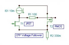
I'd turn the current sink at the top around and use a matching
IFR240,rather than its near (but never quite) compliment 9240.
This also gives the option of tapping the current sense resistor
in the middle, and turn it into an Aleph and/or AntiTriode style
(Depending which side of the sand/glass curtain you hail from)
single ended push pull active load. ...
Half the output impedance of your circuit with mere CCS load...
And still very single ended for reasons you can read at length
over in the tube or Pass threads...
I like your idea of hitching the cathode directly to the output
for feedback, almost certainly have to steal that from you.
But my output stage looks a bit different. And 220uF caps are
only for convenience of bootstrapping. Only minimally involved
in the small signal path. There might be ideas in my circuit you
could usefully rip-off as well.
My actual output is a bit more complicated class AB, but this
early class A version better illustrates basics of the topology.
The emitter drops enable the Enhancement mode MOSFETS
behave as-if depletion types. With exactly +/-.66V turn-ons.
Manufacturing variance isn't significant for the emitter drop.
Exact matching complimentary MOSFETs is not critical.
(addressing Woody's concern of post #2)
Attachments
Lumba Ogir said:Hi Wavebourn,
the number of stages being the decisive factor, there`s a substantial difference between the effects, accuracy and harmfulness of feedback. When it comes to feedback and distortion in general, it`s very much about preciseness in time, some people have considerable difficulty realizing that. While local feedback compares the output to the input of a stage, global feedback loops the output stage to the input stage of an amplifier, the correction signal affecting all the stages and vice versa.
In the two-stage compound, the control function occurs in a direct manner, offering some unique properties. The advantages are significantly greater than the disadvantages.
But the tube is an extra stage in the feedback path that has a gain, while a FET output stage has a gain as well!
")
In the original schematics both tube stage and FET stage have a voltage gain, then they are surrounded by a GNFB to bring gain to 1. Isn't it too many stages according to your principles?
And this is closer to the version of the schematic I was
searching my drives for earlier... Where both output
MOSFETs are of the same channel. And the top current
source is a fully active helper.
This version only lacked a servo.
Big difference in that my feedback was to the plate.
searching my drives for earlier... Where both output
MOSFETs are of the same channel. And the top current
source is a fully active helper.
This version only lacked a servo.
Big difference in that my feedback was to the plate.
Attachments
woody said:I see several problems. First the gate voltage needed for that
bottom mosfet will varry from device to device and also on how
hot it gets so it needs to be done with a pot.
Then the current source may have a problem. That 100 ohm
resistor from the 15v supply will let the transistor and diode
pull ~110 ma and I believe that diode is only rated at 100ma
change it to something like 5k. Or better still look at how
Nelson does these 2 things in his ZEN amplifier!
Dear Woody, I certainly will insert a pot instead of the fixed resistors. To be honest, my experience with mosfets is quite limited. So far I only used them as CCS in tube amplifiers.
My question is how stable is the point of operation of the amplifying Mosfet when currents and temperatures have settled to an equilibrium after switching on. Is a pot sufficient or would an opamp controlled servo be a better option. If suitable I would prefer the more simple solution.
The BC327 in the CCS is running at a high current to enable it to charge and discharge the gate capacitance of the IRFP9240 quickly when CCS is loaded with high audio frequencies. The higher the current the better the stability of the CCS impedance at high frequencies in the SPICE simulation.
Lumba Ogir said:KlausB,
not bad, coming up with something like that right away.
What is the preceding stage?
I don`t find those critical aspects especially bothersome (OK, some elaboration would be needed here).
Crss=160pF
Ciss=1275pF
I would try to modify it in this manner:
Lumba, probably the mosfet capacitances are not very critical concerning frequency response. However, due to the rather high tube impedance the mosfet input capacitance may slow down the feedback loop around the mosfet and the tube, creating unwanted high frequency harmonics.
Your schematic is an interesting modification. However, what I do not quite understand is the purpose of the 100 ohm resistor R8 at the drain. Is it meant as a voltage divider to cut down the amount of feedback?
The resistor is in series with the drain of the IRF240 and the output capacitor. Hence the IRFP240 cannot deliver current into the speaker.

kenpeter said:I'm just now realizing the high impedance drain end of his lower
mosfet faces in toward the center... Not a source follower circuit.
Must add some voltage gain before cathode feedback cuts the
global back to unity.
This is more or less akin to a White Cathode Follower....
Dear Kenpeter, yes, the circuit is indeed very close a white cathode follower. The idea is to give the tube as much control as possible. What I do not like so much is the idea of using the p-channel Mosfet for amplification. Concerning linearity p-channels are worse than the n-channels.
Cheers
KlausB
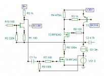
KlausB,
Crss ultimately sets the frequency response and may cause some disturbance in the feedback loop.
R8 = 100 milli-Ohm
The FET`s input impedance is infinite at low frequencies, at very high frequencies, the input capacitance messes it up, so the tube only sees those capacitances (Cgs+Crss). Certain amount of current is needed to charge them, in practice, you get away with less than ideal without being punished too hard.Lumba, probably the mosfet capacitances are not very critical concerning frequency response. However, due to the rather high tube impedance the mosfet input capacitance may slow down the feedback loop around the mosfet and the tube, creating unwanted high frequency harmonics.
Crss ultimately sets the frequency response and may cause some disturbance in the feedback loop.
R8 = 100 milli-Ohm
- Status
- This old topic is closed. If you want to reopen this topic, contact a moderator using the "Report Post" button.
- Home
- Amplifiers
- Solid State
- Single-ended mosfet-tube follower