Hey, im new here so i hope this thread is welcome here. I found this site a couple of times when donign some research about a few things. Great site!
I already posted a thread on audiokarma, but a lot of questions remain unawnserd there, so i thought maybe this would be a better forum for a ropic like this.
So here it is...
A few weeks ago i bought 2 big poweramps for a small price. 1 of them was working for 90% and the other one is broken,a nd in parts. They are basicly identical. I'm pretty sure i will be able to fix the broken amp without any big problems, but first i want to rebuild the broken amp and do a few upgrades on it.
They are both Audiolab M480's. These amps were made by the
belgium Rodec and were sold by them as the Rodec HDA 450. The Dutch Audiolab (not the British audiolab most of us know) replaced the frond of the amp and added clipping indication and sold it again as the Audiolab M480. The dutch Audiolab mainly makes speakers and cables now.
I already contacted them for more info but i wasnt able to get chematics or anything else so far. They told me the amp was used in movie theaters and bars, but also "used as a HiFi power amp voor home use, where it preformed fine". I also found a PDF witch specs of the oritional Rodec HDA 450 power amp. You can find it here. http://www.rodec.be/site/leaflet/hda450.pdf I also emailed Rodec for more info but they did not gave me any real information so far.
The amps have been rewired by a retard and were very dirty so i decided to disassemble the working amp to clean it and rewire everything.
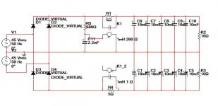
Im still a bit of a noob when it comes to hifi electronics but i had my doubts about the power suply. it had new 15.000 uF caps and no "soft start". I did a bit of reading and i decided to build a new PSU with soft start and bigger caps. When calculating a number of diffrent solutions while keeping in mind costs, preformance, and space, i came up with a design with 50.000uF of caps per chanal that had a combined rimple current of 22A. Also i defsigned a simple "soft start" using a nice 4x 20A relay i had laying around. Here is the design:
[imgatt]
I alread started to build it, and i hope i have the time to finish it this weekend. Some opinions about this PSU are very welcome.
Im going rewiring the whole amp with high quality interconnect wire and some nice speaker cable and im taking out all the internal connectors. (where are way to many of them).
Also im replacing all the electrolytic capacitors. The amps are from somewhere in the 80's and probaly where abused a lot, so i gues that wont hurt. Also someone sugested i replace the potiometers on with 10 turns models. I also ordered these.
So, like i said, i still have a few questions. Im still new to working with amps. I heard a couple of things about ajusting Bias current and DC offset. Per channal i have 3 pots (all 1K) that controll these settings i gues. I dont have a service manual or schematics. How can i in a save way find out what pot, does what, and when i fnaly know this, what setting should i go for?
The PDF i posted in the start of this post sias that the amp has a filter that filters out everything out of the 20hz-20Khz range. Is this really a good thing, or should i try to remove this filter or maybe rebuild it for a wider range? My turntable, my current amp (denon PMA-900V) and speakers go far beyond the 20khz, and im also a bit afraid that the filter might kick in before the actual 20khz range to keep the bandwith as small as possible to produce as much power as possible. I did not expirience this so far, but i did not do alot of testing yet. Any opinions on filters as these?
Also i would love to get some advice on other things in this amp (or amps in general) that can be upgraded.
Some more info on how this amp is build.
From the input on the back the input goes straight into a 100K linear pot. From here the signal goes back into a small print in te back that has a few resistors, caps. and a quad opamp IC (a motorola TL074C). Also the print has a "bridged" switch on it than can be operated fromt he back. Right nw im not sure what this print does. Maybe the filter is in here, or maybe its only a buffer and it does the things that are needed for bridge mode. It has a left and right input, and is powered by +63 and -63V. It doesnt has other inputs or exits.
The input PCB is connected to the main PCB that doesnt do much else than holding the other PCBs, house a few fuses, speaker relays, resistors for the power transitors and a few other small things.
The main PCB routes the signal from the input PCB directly to 2 PCB's that control the power transistors. The output of these 2 small PCBs goes into the power transistors and its resistors. They are 250W motorola's that can handle 20 Amp. The amp has a total of 12, so with 6 per chanal, and with both PNP an NPN thats 750W per chanal and 60amps of transistor power. Not to bad i gues. http://www.jaycar.com.au/images_uploaded/MJ150037.PDF
The siganl goes back to the main PCB that has some speaker relays and suff. Also there is another PCB mounted ont the main PCB that must have something to do with power and/or speaker protection.
Well, i hope you guys can give me some advice on what mods i can make, and help me out with my questions. Thanks!!!!
I already posted a thread on audiokarma, but a lot of questions remain unawnserd there, so i thought maybe this would be a better forum for a ropic like this.
So here it is...
A few weeks ago i bought 2 big poweramps for a small price. 1 of them was working for 90% and the other one is broken,a nd in parts. They are basicly identical. I'm pretty sure i will be able to fix the broken amp without any big problems, but first i want to rebuild the broken amp and do a few upgrades on it.
They are both Audiolab M480's. These amps were made by the
belgium Rodec and were sold by them as the Rodec HDA 450. The Dutch Audiolab (not the British audiolab most of us know) replaced the frond of the amp and added clipping indication and sold it again as the Audiolab M480. The dutch Audiolab mainly makes speakers and cables now.
I already contacted them for more info but i wasnt able to get chematics or anything else so far. They told me the amp was used in movie theaters and bars, but also "used as a HiFi power amp voor home use, where it preformed fine". I also found a PDF witch specs of the oritional Rodec HDA 450 power amp. You can find it here. http://www.rodec.be/site/leaflet/hda450.pdf I also emailed Rodec for more info but they did not gave me any real information so far.
The amps have been rewired by a retard and were very dirty so i decided to disassemble the working amp to clean it and rewire everything.
Im still a bit of a noob when it comes to hifi electronics but i had my doubts about the power suply. it had new 15.000 uF caps and no "soft start". I did a bit of reading and i decided to build a new PSU with soft start and bigger caps. When calculating a number of diffrent solutions while keeping in mind costs, preformance, and space, i came up with a design with 50.000uF of caps per chanal that had a combined rimple current of 22A. Also i defsigned a simple "soft start" using a nice 4x 20A relay i had laying around. Here is the design:
[imgatt]
I alread started to build it, and i hope i have the time to finish it this weekend. Some opinions about this PSU are very welcome.
Im going rewiring the whole amp with high quality interconnect wire and some nice speaker cable and im taking out all the internal connectors. (where are way to many of them).
Also im replacing all the electrolytic capacitors. The amps are from somewhere in the 80's and probaly where abused a lot, so i gues that wont hurt. Also someone sugested i replace the potiometers on with 10 turns models. I also ordered these.
So, like i said, i still have a few questions. Im still new to working with amps. I heard a couple of things about ajusting Bias current and DC offset. Per channal i have 3 pots (all 1K) that controll these settings i gues. I dont have a service manual or schematics. How can i in a save way find out what pot, does what, and when i fnaly know this, what setting should i go for?
The PDF i posted in the start of this post sias that the amp has a filter that filters out everything out of the 20hz-20Khz range. Is this really a good thing, or should i try to remove this filter or maybe rebuild it for a wider range? My turntable, my current amp (denon PMA-900V) and speakers go far beyond the 20khz, and im also a bit afraid that the filter might kick in before the actual 20khz range to keep the bandwith as small as possible to produce as much power as possible. I did not expirience this so far, but i did not do alot of testing yet. Any opinions on filters as these?
Also i would love to get some advice on other things in this amp (or amps in general) that can be upgraded.
Some more info on how this amp is build.
From the input on the back the input goes straight into a 100K linear pot. From here the signal goes back into a small print in te back that has a few resistors, caps. and a quad opamp IC (a motorola TL074C). Also the print has a "bridged" switch on it than can be operated fromt he back. Right nw im not sure what this print does. Maybe the filter is in here, or maybe its only a buffer and it does the things that are needed for bridge mode. It has a left and right input, and is powered by +63 and -63V. It doesnt has other inputs or exits.
The input PCB is connected to the main PCB that doesnt do much else than holding the other PCBs, house a few fuses, speaker relays, resistors for the power transitors and a few other small things.
The main PCB routes the signal from the input PCB directly to 2 PCB's that control the power transistors. The output of these 2 small PCBs goes into the power transistors and its resistors. They are 250W motorola's that can handle 20 Amp. The amp has a total of 12, so with 6 per chanal, and with both PNP an NPN thats 750W per chanal and 60amps of transistor power. Not to bad i gues. http://www.jaycar.com.au/images_uploaded/MJ150037.PDF
The siganl goes back to the main PCB that has some speaker relays and suff. Also there is another PCB mounted ont the main PCB that must have something to do with power and/or speaker protection.
Well, i hope you guys can give me some advice on what mods i can make, and help me out with my questions. Thanks!!!!
Attachments
![dsc00195 [800x600] (2).jpg](/community/data/attachments/121/121202-4e77763fdd1a428d4220ee89e3c40c0d.jpg)
![dsc00198 [800x600] (2).jpg](/community/data/attachments/121/121210-3fc7bcd847aa12f141cb4cdd932ec0b9.jpg)
![dsc00201 [800x600] (2).jpg](/community/data/attachments/121/121215-c5122a34db81059c948ee3de23df4f8c.jpg)
![dsc00243 [800x600] (2).jpg](/community/data/attachments/121/121219-65b9a9ec7754a918d73237a97bce16a0.jpg)
![dsc00252 [800x600].jpg](/community/data/attachments/121/121225-b0ce7e3629798b4df1b8a5391b3e792b.jpg)
![dsc00250 [800x600].jpg](/community/data/attachments/121/121231-62131689944e6b8517bb6709e4be3b8f.jpg)
![dsc00246 [800x600] (2).jpg](/community/data/attachments/121/121236-3220f8877933248d5d6af0be33bd207f.jpg)
Hi,SuperKris said:The PCB small pcb that I guess is used for speaker/power protection
does R22 run very hot? The PCB is scorched, but that might be from a previous failure.
If it runs hot enough to scorch the PCB then change it for a very much higher power device and move it further from the PCB.
The adjacent transistor must be getting a roasting!
Hi,SuperKris said:The parts for the new PSU im building
the cooling plate between the two power resistors is not doing much good. It's being heated from both sides and little free area left to dissipate any heat!
Hi,SuperKris said:The back
check that ground switch and find out what is being switched.
The exposed conductive parts must be connected to the Safety Earth.
The Protective Earth wire (the third wire in the mains cable) must be permanently connected to chassis.
I don't understand the PSU schematic.SuperKris said:[B Audiolab M480's. These amps were made by the
belgium Rodec 0........................ it does the things that are needed for bridge mode. It has a left and right input, and is powered by +63 and -63V. ......................
The main PCB routes the signal from the input PCB directly to 2 PCB's that control the power transistors. The output of these 2 small PCBs goes into the power transistors and its resistors. They are 250W motorola's that can handle 20 Amp. The amp has a total of 12, so with 6 per chanal, and with both PNP an NPN thats 750W per channel and 60amps of transistor power. [/B]
Is this a copy of the original or is it your own design?
+-63Vdc from 40Vac does not sound right.
Most get between +-56Vdc and +-59Vdc from 40Vac transformers.
3pair of MJ15003/4 can drive severe 8ohm speakers all day if the heatsinks stay below 100degC.
4ohm loads can be driven in all domestic situations provided the heatsinks stay below 50degC.
This amp cannot drive 4ohms in Bridged mode.
The restriction applied to 4ohms in stereo mode applies to 8ohms in Bridged mode. Keep the sinks below 50degC and don't use it for PA or disco applications without adding sink temperature monitoring and/or over temp switch off.
Thanks for you posts!
Its not a cooling plate, its only a place to mount the resistors. I have limited space in the PSU cage, and this is the only place i had room for them. They are only used to load the PSU caps for max 2 sec. They have to eat a huge amount of power, but that only for a really short time. No cooling needed here.
The PE is always connected to the chassis, and alway by a cap (i think its 22nF) connected to the ground of the electronics. when te switched is turned on, the PE is get connected to the ground of the electronics with a 1 Ohm resistor.
I dont know is this is oritional. The drawing on the back of the amp suggest that i might have been changed into this. It kinda looks like the switch has something to do with the XLR connectors, but the way i got the amp it was not wired that way. I dont know anything about the way XLR connectors are usualy used.
I didnt test enough to really awnser the question at at this point. However, the same print in the 2nd amp isnt burned as bad, so i gues this is from a previous failure, or maybe a small fault in the amp. This amp has already been repaird 1 or multiple times. There are a few parts that have been replaced.AndrewT said:does R22 run very hot? The PCB is scorched, but that might be from a previous failure.
If it runs hot enough to scorch the PCB then change it for a very much higher power device and move it further from the PCB.
The adjacent transistor must be getting a roasting!
AndrewT said:the cooling plate between the two power resistors is not doing much good. It's being heated from both sides and little free area left to dissipate any heat!
Its not a cooling plate, its only a place to mount the resistors. I have limited space in the PSU cage, and this is the only place i had room for them. They are only used to load the PSU caps for max 2 sec. They have to eat a huge amount of power, but that only for a really short time. No cooling needed here.
AndrewT said:check that ground switch and find out what is being switched.
The exposed conductive parts must be connected to the Safety Earth.
The Protective Earth wire (the third wire in the mains cable) must be permanently connected to chassis.
The PE is always connected to the chassis, and alway by a cap (i think its 22nF) connected to the ground of the electronics. when te switched is turned on, the PE is get connected to the ground of the electronics with a 1 Ohm resistor.
I dont know is this is oritional. The drawing on the back of the amp suggest that i might have been changed into this. It kinda looks like the switch has something to do with the XLR connectors, but the way i got the amp it was not wired that way. I dont know anything about the way XLR connectors are usualy used.
Re: Re: Need some advice rebuilding/upgrading 2 power amps.
Thanks for your post!
The PSU design is my own design. the 550VA transformer has two 45V outputs, so 45 root 2 gives you 63.6V top. minus around 1.2V that gets lost in the rectifier, that 62-63V top, im nut sure how big the AC rimple will be, but because im using a huge 50.000uF in caps, i dont think it will be much more than 2V, so the PSU output should be around 61-62V average
Maybe you could tell me a little bit more about driving 4 speakers with these transistors. The specs in the PDF i posted claim it is a PA amp, and they also claim it will do 4 ohm fine while using the amp as a PA. Also it claims it can do 4 ohm bridged just fine. Before i bought these amps i did some reading ofcourse, and everything i found, is that they are very reliable, also when used with 4 ohm and as a PA.
Im planning to buy some big infinity's in the future and bi-amp with these. The old infinitys are know for their huge demand of power and currend, and are very often used with PA amps.
AndrewT said:I don't understand the PSU schematic.
Is this a copy of the original or is it your own design?
+-63Vdc from 40Vac does not sound right.
Most get between +-56Vdc and +-59Vdc from 40Vac transformers.
3pair of MJ15003/4 can drive severe 8ohm speakers all day if the heatsinks stay below 100degC.
4ohm loads can be driven in all domestic situations provided the heatsinks stay below 50degC.
This amp cannot drive 4ohms in Bridged mode.
The restriction applied to 4ohms in stereo mode applies to 8ohms in Bridged mode. Keep the sinks below 50degC and don't use it for PA or disco applications without adding sink temperature monitoring and/or over temp switch off.
Thanks for your post!
The PSU design is my own design. the 550VA transformer has two 45V outputs, so 45 root 2 gives you 63.6V top. minus around 1.2V that gets lost in the rectifier, that 62-63V top, im nut sure how big the AC rimple will be, but because im using a huge 50.000uF in caps, i dont think it will be much more than 2V, so the PSU output should be around 61-62V average
Maybe you could tell me a little bit more about driving 4 speakers with these transistors. The specs in the PDF i posted claim it is a PA amp, and they also claim it will do 4 ohm fine while using the amp as a PA. Also it claims it can do 4 ohm bridged just fine. Before i bought these amps i did some reading ofcourse, and everything i found, is that they are very reliable, also when used with 4 ohm and as a PA.
Im planning to buy some big infinity's in the future and bi-amp with these. The old infinitys are know for their huge demand of power and currend, and are very often used with PA amps.
Hi,
those tiny heatsinks do not indicate PA duty to me.
Certainly NEVER use this amp bridged into 4ohms.
Domestic duty is a completely different ballpark.
We generally listen to average music levels between 10dB and 30dB below the maximum the amplifier is capable of.
I try to aim for >20dB below maximum, to allow dynamic source material to never clip the output of the amplifiers nor any preceding part of the amplifying chain.
If your amp is capable of 300W into 4r0 then your average listening level is likely to be around 3W.
What is the sensitivity of your speakers?
What SPL will they produce with a 3W input?
I think you'll find that is quite loud.
45Vac will have an unloaded voltage of Vac * regulation% * supply voltage/nominal voltage.
If your supply is running at 6% over nominal and the regulation of your transformer is 4% then the unloaded voltage from the secondary is ~1.04 * 1.06 * 45 ~=49.6Vac.
The DC voltage across the smoothing caps when unloaded will be 49.6 * sqrt(2) - diode Vdrop. At low current the Vdrop can be around 400mV.
The maximum smoothing capacitance voltage will be ~69.7Vdc.
This is far too high for reliability of 63V capacitors. You will need 75V or 80V or 100V capacitors.
The maximum transformer voltage for 63V capacitors is ~41Vac.
The metal clad resistors you have chosen require a large heatsink to get the dissipation rating they are capable of.
Without a heatsink they will heat up very rapidly if you pass a high current through them.
A wire wound ceramic clad power resistor would be much better in this location.
If the continuous current through these resistors is 1A then the dissipation will be 1^2 * R = 5W. This is hot. If you pass that current continuously then the voltage drop will be 1 * R = 5V. You have forced the output voltage of the PSU to drop by 5V when asking it to meet a demand of just 1A. Modulation of the supply voltage to your amplifier is not good.
If you want CRC filtering of your PSU, then reduce your resistors to <=0r5. Now 5W wire wounds will pass 3Apk without difficulty, but not continuously. They will drop just 1.5Vpk when passing 3Apk.
The first C of a CRC filter is subjected to enormous ripple current. This capacitor will overheat if you provide inadequate ripple capacity.
The second C of a CRC filter has much less need for ripple current. Instead it's prime duty is to supply short term transient current to match the demands of the amplifier. This requires a good sounding capacitor here. Low ESR and low ESL seems to meet the quality requirement.
Measure the resistance between the earth pin of your plug top and the chassis. It should read 0r0 or as near as you can read.
Measure the resistance from the earth pin of your plug top to the main audio ground, the speaker return terminal would do.
Now flick the ground switch and read these resistances again.
Report your results.
Measure the resistance from the earth pin of your plug top to the main audio ground, the speaker return terminal would do.
Now flick the ground switch and read these resistances again.
Report your results.
AndrewT said:Hi,
those tiny heatsinks do not indicate PA duty to me.
Certainly NEVER use this amp bridged into 4ohms.
Domestic duty is a completely different ballpark.
We generally listen to average music levels between 10dB and 30dB below the maximum the amplifier is capable of.
I try to aim for >20dB below maximum, to allow dynamic source material to never clip the output of the amplifiers nor any preceding part of the amplifying chain.
If your amp is capable of 300W into 4r0 then your average listening level is likely to be around 3W.
What is the sensitivity of your speakers?
What SPL will they produce with a 3W input?
I think you'll find that is quite loud.
45Vac will have an unloaded voltage of Vac * regulation% * supply voltage/nominal voltage.
If your supply is running at 6% over nominal and the regulation of your transformer is 4% then the unloaded voltage from the secondary is ~1.04 * 1.06 * 45 ~=49.6Vac.
The DC voltage across the smoothing caps when unloaded will be 49.6 * sqrt(2) - diode Vdrop. At low current the Vdrop can be around 400mV.
The maximum smoothing capacitance voltage will be ~69.7Vdc.
This is far too high for reliability of 63V capacitors. You will need 75V or 80V or 100V capacitors.
The maximum transformer voltage for 63V capacitors is ~41Vac.
I have no idea if some parts of the amp might be underpowered for PA uses, but the amp is definatly sold as a PA amp, and i have read good thing about this amp preforming as PA amp. Also for 4 Ohm. To me the heatsinks dont seem very small. Together they are bigger than any i ever seen actualy, but like i said, im a noob
 Anyway. im not going to use it as a PA anyway.
im not plannning to use this amp on my current speakers becasue that would be overkill. Like i said. I would like to buy some old infinitys in the future and they jsut need sick amounts of power. They are also not very sensitive with all below 90dB.
i'm not sure what your saying about the transformer voltages... As far as i know they have a output of 45V loaded and that transforms into 63V top. The oritonal caps in both amps are 63V too. It seems that the caps of 1 of the amps has already been replaced because of a destructive explosion
But hey, they are around 20 y/o so i thats not to strange for a PA amp. The other amp thats also around 20y/o looks like its still using its oritional caps. They are all 63V. Personaly i would like to have a higher voltage rating, but at this stage i dont want to spen to much money. Going with 100V caps is amost 2 times as expenive, and i dont have enough room to place 50.000uF of 100V caps.AndrewT said:The metal clad resistors you have chosen require a large heatsink to get the dissipation rating they are capable of.
Without a heatsink they will heat up very rapidly if you pass a high current through them.
A wire wound ceramic clad power resistor would be much better in this location.
If the continuous current through these resistors is 1A then the dissipation will be 1^2 * R = 5W. This is hot. If you pass that current continuously then the voltage drop will be 1 * R = 5V. You have forced the output voltage of the PSU to drop by 5V when asking it to meet a demand of just 1A. Modulation of the supply voltage to your amplifier is not good.
If you want CRC filtering of your PSU, then reduce your resistors to <=0r5. Now 5W wire wounds will pass 3Apk without difficulty, but not continuously. They will drop just 1.5Vpk when passing 3Apk.
The first C of a CRC filter is subjected to enormous ripple current. This capacitor will overheat if you provide inadequate ripple capacity.
The second C of a CRC filter has much less need for ripple current. Instead it's prime duty is to supply short term transient current to match the demands of the amplifier. This requires a good sounding capacitor here. Low ESR and low ESL seems to meet the quality requirement.
The resistors are only to load the caps at startup. They will be bridged by the relay after 1.5 - 2 seconds. Their only purpose is to not pop the house fuses or wear down the on/of switch and/or regulator. Im never hreard about a CRC filter before actualy
AndrewT said:Measure the resistance between the earth pin of your plug top and the chassis. It should read 0r0 or as near as you can read.
Measure the resistance from the earth pin of your plug top to the main audio ground, the speaker return terminal would do.
Now flick the ground switch and read these resistances again.
Report your results.
Its quite funny that you told me to meassure that. I found that the resistor that connects the chassis/PE to the electronics GND is broken. It looks fine, but it shows infinity ohm.
But to awnser youw questions, there is no resistance (0 ohm) between the chasis and the PE. With the switch in the upper position (open mode) the chassis/PE is coupled to the electronics ground with a 22nF cap. When the switch is in the lower position (closed mode), the chassis/PE is still connected to the electronics ground trough the 22nF cap, but now also by a 10 Ohm resistor. ( i said 1 ohm before, but it brown/black/black, so that should be 1 Ohm) Also like i said before, i have no idea if this is oritional.
- Status
- This old topic is closed. If you want to reopen this topic, contact a moderator using the "Report Post" button.
- Home
- Amplifiers
- Solid State
- Need some advice rebuilding/upgrading 2 power amps.