Hi All,
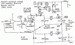
I do apologise for a rather rough drawing. However it is quite correct and could be built. I did omit the voltage amplifer, as it is a matter of taste and there are plenty of circuits around. This circuit will work both inside and outside the NFB loop. It is a proper follower with a high input impedance and low output impedance (aboul 0.2 Ohm). This circuit is close to the very first one I've designed in 1992. Since then it's versions (considerably improved and developed) were used by me in a series of Creek Audio Limited amplifiers (I was a chief engineer there till the end of last year) , starting from 4240 and including latest 5350 and A50 amps. I did publish the original idea in the RadioHobby magazine (in Russian) in 1998. If you DO understand how it works, well done. Many people don't. However it performs nicely and could be even happily biased into class A providing sufficient heatsinking. It is NOT short circuit protected, so take care about that. Power supply with the transistors shown could be between +/- 25-35 V .
Enjoy.
Al
Attachments
Hi Al. This is right up my alley at the present moment. Have been doing *lots* of experiments withthis topology. I like the way Q1 Vgs partially counters Q4 Vgs so there is no output offset; something I had been pondering. Instead of the current source at the top, my ccts had a resistor fed from a rail that rode on the output. What is the purpose of D2 & D3? It would seem that this circuit could be scaled up to heroic proportions without much trouble. 
X-PRO,
this looks nice to me. I have lot of IRFP250N, and IRFP150N. I think they are useful for this project. Do You think that IRF9510, or 9610 suitable as Q1?
I want to use this amplifier with +/-65-70V to get some 4-500W. I want to use valves as voltage amplifier. E88CC with two stage common cathode amplifier looks nice.
Add some DC servo to the gate of Q1 can helps to keep the output at 0.
Sajti
sajti said:X-PRO,
this looks nice to me. I have lot of IRFP250N, and IRFP150N. I think they are useful for this project. Do You think that IRF9510, or 9610 suitable as Q1?
I want to use this amplifier with +/-65-70V to get some 4-500W. I want to use valves as voltage amplifier. E88CC with two stage common cathode amplifier looks nice.
Add some DC servo to the gate of Q1 can helps to keep the output at 0.
Sajti
hi Sajti
Good thinking - one of my first prototypes in 1992 did actually work with IRFP250 and 9610. Don't forget to put 9610 on a heatsink, reduce R8 and R10 to 150R (1W 1%) or 2x 0.5W 300R in parallel, increase R7 and R9 to 68-100R. For +/-65-70V you'll need to use 9610 (200V) as 9510 is only 100V device. And you'll need to replace Q2 with 9610 as well, on a heatsink, replace R4 with 1.2V bandgap reference (it will give you perfect temperature compensation for IRFP250's), increase power on R6 to 3W and reduce R3 to 24 Ohm or put (better) an additional resistor in parallel to R3 RV1 chain, say about 47 Ohm. I also would advise you to use a small inductor on the output (1-3 uH) in parallel with 1 Ohm resistor. Servo is also a good idea and the circuit will work fine with a valve VA, just provide for some voltage limiting so not to overvoltage the input too much.
Good luck!
Al
x-pro said:
put (better) an additional resistor in parallel to R3 RV1 chain, say about 47 Ohm.
Al
Sorry, I think that this value should be more like 68-75 Ohm, otherwise the adjustment range may be not enough. Try with R3 33 Ohm first and without additional resistor - it should be safer
.Also for RV1 position better to use a cermet trimmer pot with at least 0.5W rating.
Al
Thanks for the information.
One more question:
Is it possible to use higher positive rail for the Q2-Q3 network, I think this will gives more output voltge swing.
If I use valve input stage there will be no problem to put the whole current regulator network 20-25V over the positive rail.
To avoid the input overload I will use two zener+diode series networks to the power supply rails.
I think to use higher value source resistors, say 0.33-0.47, to get better bias regulation. With 16 output devices 0.47 ohms is not too much.
Sajti
sajti said:Thanks for the information.
One more question:
Is it possible to use higher positive rail for the Q2-Q3 network, I think this will gives more output voltge swing.
If I use valve input stage there will be no problem to put the whole current regulator network 20-25V over the positive rail.
To avoid the input overload I will use two zener+diode series networks to the power supply rails.
I think to use higher value source resistors, say 0.33-0.47, to get better bias regulation. With 16 output devices 0.47 ohms is not too much.
Sajti
Hi Sajti,
It is not just possible, but very desirable - actually i did it in that prototype circuit. 10V-20V is enough. Input limiting could be done just by adding one more diode from the input to the positive rail of the output devices. higher source resistors OK, if you will use several devices. You may find you'll need to increase the current through the driver (9610) to be able to drive more of these. Just reduce the value of the resistors further and calculate the power dissipation carefully, especially on Q2.
Al
M.Y. said:hi X-PRO,
if the Q1 could be used irf610?if so, the circuit will do any change?
thinks,
Yes, IRF610 may be used in Q1 position without changes.
x-pro
sajti said:I think, You mean IRF9610....
Sajti
Thanks! Obviously I thought about IRF9610
- I was half asleep replying. However N-channel device (like IRF610) could be used in Q1 position (!) thought the circuit will become an inverting and amplifying stage and will require an appropriate driver arrangements and input biasing. x-pro
Mr. AL
Cause my friend's question,Could you tell me the type of the Creek 4240's power devices?...if anyone could share the schematic of Creek 4240,will be much more appreciated.my e-mail is jmxg007@tom.com
thanks
X.G.
my friend's question posted here.
http://www.hifidiy.net/dispbbs.asp?boardID=2&ID=6483&skin=0
An externally hosted image should be here but it was not working when we last tested it.
X.G. said:Mr. AL
Cause my friend's question,Could you tell me the type of the Creek 4240's power devices?...if anyone show me the schematic of Creek 4240,will be much more appreciated.
thanks
X.G.
Early 4240 (1993-94) used BUK553-100A, later BUK555-100A/B was used.
Drop me a mail and I'll send you 4240 diagram - it was published by me in 1998 in "RadioHobby" magazine. Better if you'll check and mail me the board revision number, as there were several revisions to 4240.
Cheers
Alex
X.G. said:Thanks a lot,Mr. A L
I will e-mail to you after I get the the board revision number.
Best wish from China.
X.G.
Now I can see the revision number on the photo - it is V1.1
Send me a mail and I'll send you the schematics for it.
Cheers
Alex
.... but then you'll have to activate the email button of yours... which is disabled right now...x-pro said:You can always send an email through the forum - click on "x-pro" on the left and choose "send email"
Cheers
Alex
- Status
- This old topic is closed. If you want to reopen this topic, contact a moderator using the "Report Post" button.
- Home
- Amplifiers
- Solid State
- N-channel only output devices in a power follower.