Thanks Rafael, switched npn for pnp, no diffrence, then realized I changed the LTP degeneration from 100 ohms to 33. Changed back and everythings better. Never new these Rs could effect stability so much, then remembered someone mentioning increaseing the LTP bias current affects stability, These Rs shoudnt affect the bias current but both current and these Re's affect the LTP Gm. Does this make sense? Learned alot today!
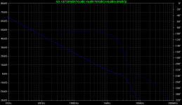
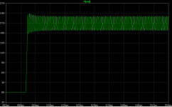
Heres the new plots.
Heres the new plots.
Attachments
The standard way of making an amplifier stable is dominant pole compensation, implemented with the Miller capacitor. This works by adding a pole much lower in frequency than any others, so it dominates the frequency response and you get a nice smooth roll off. Of course this only works if all other poles are much higher in frequency, which means the input stage must have high enough bandwidth. The bandwidth can be increased by increasing the quiescent current (up to a point), or increasing the degeneration.cbdb said:...Never new these Rs could effect stability so much, then remembered someone mentioning increaseing the LTP bias current affects stability, These Rs shoudnt affect the bias current but both current and these Re's affect the LTP Gm. Does this make sense? Learned alot today!..
Do as the original circuit. ok!cbdb said:switched npn for pnp, no diffrence
Yes, reduces the gain, plus increases in frequency response in open-loop. Which can increase the feedback negative for high frequencies, look plotcbdb said:other then losing a few db of open loop gain
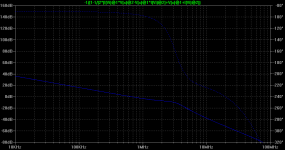
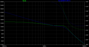
Put your graphics from 10Hz, are difficult to understand beginning with high frequencies
There was very little change (if any) in open loop bandwidth. The chage in LTP Re's moves the second pole to a higher F increasing phase margin, but open loop BW is dominated by the first pole caused by Cdom (the Miller cap on the VAS) which hasnt changed. (a question: I though the second pole was usually caused by the large output caps, not the input stage?)
You can find more info and LTSpice implementation of loop gain measurement on Frank Wiedman's web site: <http://www.geocities.com/frank_wiedmann/loopgain.html>.
These SPICE circuits can be found in the LTSpice Yahoo Group, under Files/Examples/Educational/LoopGain_Probe.
Very useful and lots of fun!
Peter
These SPICE circuits can be found in the LTSpice Yahoo Group, under Files/Examples/Educational/LoopGain_Probe.
Very useful and lots of fun!
Peter
HELP How do I increase the freq of the first internal pole
Thanks for your replies, I think I now know how to determine stability using spice. Now lets get to the crux. Gettting the most gain and open loop bandwidth while maintainig stability ( I believe this is how you get low THD at high freq. (any f above the Cdom pole f )) Please correct me if Im wrong. What causes instability is the first internal pole (not sure what else to call it) of the amp (the one you get with no Cdom (Miller cap)). So to increase HF gain (and decrease HF THD) you have to push this pole to a higher f. This is where I seek help. I suppose its the Cob of the transitors that limits this f, but I am wondering if there are ways around this ( like the increase of the LTP bias or degeneration Rs does). In my Blameless experments it looks like this pole is caused by the input stage, is this corrrect? I thought it would be the large output Transistors. These poles are low pass filters so I am now thinking the associated Rs (internal and ex) play a big role and may give a chance to "cheat" the Cob (like LTP degeneration Rs do). I know the Cob is Vce dependent, but is it also Ic dependent?
I know this is a big question, any input would help.
Re: HELP How do I increase the freq of the first internal pole
o
o
You can also increase the bias in VAS can increase the bandwidth.
can also try Miller two-poles, more what's in the book Self is unstable in square wave, the members of this forum Edmond and Andy_C resolved , they can respond you better about two-poles Miller
o
o
Not cause instability what can happen brute rolloff that may have a bad phase margin, and the phase margin is very dependent on the transistors used.cbdb said:What causes instability is the first internal pole (not sure what else to call it) of the amp (the one you get with no Cdom (Miller cap)).
o
Open loop gain is determined by voltage and current, If you decrease the voltage and keep the current(degeneration), increase bandwidth more voltage gain decreases in open loopcbdb said:
So to increase HF gain (and decrease HF THD) you have to push this pole to a higher f. This is where I seek help. I suppose its the Cob of the transitors that limits this f, but I am wondering if there are ways around this ( like the increase of the LTP bias or degeneration Rs does).
You can also increase the bias in VAS can increase the bandwidth.
can also try Miller two-poles, more what's in the book Self is unstable in square wave, the members of this forum Edmond and Andy_C resolved , they can respond you better about two-poles Miller
o
All stages influence, more who does the most cutting (first pole) is the stage Vas, that is what has higher gaincbdb said:
In my Blameless experments it looks like this pole is caused by the input stage, is this corrrect?
more who does the most cutting (first pole) is the stage Vas
OK I mean besides the VAS, this is forced to be first pole with Cdom then the second pole is what matters for stability (its what takes you to -180 degrees) Sorry maybe the question wasnt clear.
I understood, first stage has high-bandwidth (the gain is somewhat), not causing the poles limiting.cbdb said:
OK I mean besides the VAS, this is forced to be first pole with Cdom then the second pole is what matters for stability (its what takes you to -180 degrees) Sorry maybe the question wasnt clear.
Vas can cause the first and second pole by limiting the source of current for example.
Re: HELP How do I increase the freq of the first internal pole
The open-loop bandwidth, defined as the frequency at which the open-loop gain is 3 dB down from its DC value, is not by itself important to stability. In fact, both the open-loop bandwidth and the DC open-loop gain are not well controlled in a typical amplifier. However the product of these, called the gain-bandwidth product (GBW), is very well controlled and can be made almost completely independent of device parameters. Here's how it works. If you take the gain-bandwidth product and divide it by the nominal closed-loop gain as set by the feedback resistors, this gives you the unity loop gain frequency. This is sometimes called the ULG freq, which is the frequency for which the magnitude of the loop gain is 0 dB. To get the most feedback and lowest distortion, one shoots for the highest unity loop gain frequency that's consistent with good stability and clean transient response.
The GBW in Hertz is given by gm / (2 * pi * Cdom), where gm is the input stage transconductance and Cdom is the Miller compensation cap.
This is usually called the first non-dominant pole.
This is not actually what it is. To understand why, it's important to understand how Miller compensation achieves pole splitting. To learn more about this, I'd recommend reading The Monolithic Operational Amplifier: A Tutorial Study by Solomon. This is a classic article that originally appeared in the IEEE Journal of Solid State Circuits. You should probably skip over the section on thermal feedback effects, as it's specific to ICs, and according to those in the know (Scott Wurcer among others), is no longer a problem in ICs anyway. There's a good discussion of pole splitting in that article. The long and short of it is that not only does Cdom reduce the frequency of the dominant pole of the VAS, but it also increases the frequency of its non-dominant pole. This is beneficial for stability on two fronts.
Actually, you want to push the unity loop gain frequency up, as mentioned above. Recall that this is the GBW divided by the nominal closed-loop gain (CLG). So for a fixed CLG, you want to maximize the GBW. When you increased the input stage emitter resistor, this reduced the GBW and therefore the ULG freq, stabilizing the amp. The two things you play with to make this happen are gm and Cdom - the two things that determine the GBW.
I don't think so. The bandwidth of the transconductance of the input stage should be quite large. You can look at the input stage by itself, separated from the rest of the amp by loading its current mirror output with a DC voltage source of maybe 2 VDC to the negative rail (to "fake" the bias voltage of the VAS base). Then look at the frequency response from the difference-mode input voltage to the current in this 2V source. It should be flat out to the MHz range. Other experiments you can do are to replace the output stage with a unity gain VCVS ("E" source) to see if your stability problem goes away.
That's all I can think of for now. Once you "grok" the GBW concept and its relationship to the ULG freq and the CLG, the stability issues should fall into place.
cbdb said:Thanks for your replies, I think I now know how to determine stability using spice. Now lets get to the crux. Gettting the most gain and open loop bandwidth while maintainig stability ( I believe this is how you get low THD at high freq. (any f above the Cdom pole f ))
The open-loop bandwidth, defined as the frequency at which the open-loop gain is 3 dB down from its DC value, is not by itself important to stability. In fact, both the open-loop bandwidth and the DC open-loop gain are not well controlled in a typical amplifier. However the product of these, called the gain-bandwidth product (GBW), is very well controlled and can be made almost completely independent of device parameters. Here's how it works. If you take the gain-bandwidth product and divide it by the nominal closed-loop gain as set by the feedback resistors, this gives you the unity loop gain frequency. This is sometimes called the ULG freq, which is the frequency for which the magnitude of the loop gain is 0 dB. To get the most feedback and lowest distortion, one shoots for the highest unity loop gain frequency that's consistent with good stability and clean transient response.
The GBW in Hertz is given by gm / (2 * pi * Cdom), where gm is the input stage transconductance and Cdom is the Miller compensation cap.
Please correct me if Im wrong. What causes instability is the first internal pole (not sure what else to call it) of the amp...
This is usually called the first non-dominant pole.
...(the one you get with no Cdom (Miller cap)).
This is not actually what it is. To understand why, it's important to understand how Miller compensation achieves pole splitting. To learn more about this, I'd recommend reading The Monolithic Operational Amplifier: A Tutorial Study by Solomon. This is a classic article that originally appeared in the IEEE Journal of Solid State Circuits. You should probably skip over the section on thermal feedback effects, as it's specific to ICs, and according to those in the know (Scott Wurcer among others), is no longer a problem in ICs anyway. There's a good discussion of pole splitting in that article. The long and short of it is that not only does Cdom reduce the frequency of the dominant pole of the VAS, but it also increases the frequency of its non-dominant pole. This is beneficial for stability on two fronts.
So to increase HF gain (and decrease HF THD) you have to push this pole to a higher f. This is where I seek help.
Actually, you want to push the unity loop gain frequency up, as mentioned above. Recall that this is the GBW divided by the nominal closed-loop gain (CLG). So for a fixed CLG, you want to maximize the GBW. When you increased the input stage emitter resistor, this reduced the GBW and therefore the ULG freq, stabilizing the amp. The two things you play with to make this happen are gm and Cdom - the two things that determine the GBW.
I suppose its the Cob of the transitors that limits this f, but I am wondering if there are ways around this ( like the increase of the LTP bias or degeneration Rs does). In my Blameless experments it looks like this pole is caused by the input stage, is this corrrect?
I don't think so. The bandwidth of the transconductance of the input stage should be quite large. You can look at the input stage by itself, separated from the rest of the amp by loading its current mirror output with a DC voltage source of maybe 2 VDC to the negative rail (to "fake" the bias voltage of the VAS base). Then look at the frequency response from the difference-mode input voltage to the current in this 2V source. It should be flat out to the MHz range. Other experiments you can do are to replace the output stage with a unity gain VCVS ("E" source) to see if your stability problem goes away.
That's all I can think of for now. Once you "grok" the GBW concept and its relationship to the ULG freq and the CLG, the stability issues should fall into place.
- Status
- This old topic is closed. If you want to reopen this topic, contact a moderator using the "Report Post" button.
- Home
- Amplifiers
- Solid State
- General power amplifier stability discussion (using Spice)