I have design simple amp at http://nanhifi.tripod.com/m60bpoweramp.htm have a to get the detail.
I want a recomendation for upgrading this power amp. I fell that this amp have still lack in most cases.
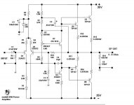
This circuit open for any modifieder. I originaly design by me:
I want a recomendation for upgrading this power amp. I fell that this amp have still lack in most cases.
This circuit open for any modifieder. I originaly design by me:
Attachments


I just get noticed
Thanks for your information.
About the input pair i just get noticed there a big wrong on the symbol (arrow one) it should PNP. Yes the current source not avaible. I hope that you can make me one. And the value for R3 and R4. What are your suggestion? the exect value maybe 470R or 220R. Are there will be major banefit on that value?
I have build this amp and a big problem face in the bias current. I cannot even change the bias or Quinsent current.
The connection of R8 is wrong... the lower connection should go to the emitter of Q3, not the base of the VAS.
Currently your circuit doesn't have any feedback either. R3 and R4 should be around 100 ohms and then you have to use a resistor (22k?) or preferably a current source between the zener and their junction. If you use a current source the voltage stabiliser probably won't be needed.
R5 looks a bit high to me. The bias current for the VAS is about 5mA, giving 500mV over R11 and also R5. Only 70µA will flow through it when the output is at 0V.
Does the output stage have enough current gain? There is only 5mA of drive available, but those are darlington transistors so maybe it is okay after all...
for good current source reading material refering to rod elliot website at sound.au.com refer to his project 3 a for inspiration
IMHO used two transistor for your darlington sounds better
bd139 with mj15003/mj21193/sc5200 i think/ mjl3281 npn
bd140 with mj15004/mj21194/sa can' t remember / mjl1302 pnp
or u can used the jap transistor u design with for the driver
if you can remove c3 would be good, as this is in the feedback loop, its purpose for providing a more stable dc at output, but colorizes the sound
with r4 and r3 reduce 100 ohm it would be better. this resistors are for to allowing some local feedback in the ltp to balance the gain of two different transistors sa872
omit the c3??
Thank for this info. I just never seen before any circuit that not using the C3 basicly. I hope you can give me a example circuit that do not use the C3 for feedback loop. It is something new to me. I want to build it one.
NickC said:for good current source reading material refering to rod elliot website at sound.au.com refer to his project 3 a for inspiration
IMHO used two transistor for your darlington sounds better
bd139 with mj15003/mj21193/sc5200 i think/ mjl3281 npn
bd140 with mj15004/mj21194/sa can' t remember / mjl1302 pnp
or u can used the jap transistor u design with for the driver
if you can remove c3 would be good, as this is in the feedback loop, its purpose for providing a more stable dc at output, but colorizes the sound
with r4 and r3 reduce 100 ohm it would be better. this resistors are for to allowing some local feedback in the ltp to balance the gain of two different transistors sa872
Thank for this info. I just never seen before any circuit that not using the C3 basicly. I hope you can give me a example circuit that do not use the C3 for feedback loop. It is something new to me. I want to build it one.
- Status
- This old topic is closed. If you want to reopen this topic, contact a moderator using the "Report Post" button.
- Home
- Amplifiers
- Solid State
- Any Suggestion Upgrade My Amp