AndrewT said:Hi Ken,
your calculations are bonkers.
You have bootstrapped the drive to GS1 & GS2.
The maximum output will be <+-Vsupply.
Your calculations show 35Vrms from +-25Vdc.
Impossible for the circuit you have posted.
My ideas are always bonkers, whats news about that?
35Watts RMS Sine, 70Watts RMS Square. Into 8 ohms...
Where do you ever read me to say 35Volts RMS???
Expected peak swing is only about +/-23.6V. Even with
drives strapped well above the rail, RDSon or VCEsat in
the final output totem will inevitably drop some voltage.
23.6VPeak * SQR(2)/2 = 16.7VRMS
16.7VRMS * 16.7VRMS / 8ohms = 35 Watts RMS
Lower frequencies need bigger bootstrap caps. But these
are largely not "signal coupling", barely matters they might
be cheap non-linear and/or electrolytic monstrosities...
Any loading effect they have upon the nodes from where
they are driven and/or pull up or down, is also where local
error corrections are strongest. A conspiracy to hide them....
that is much more believable from +-25Vdc.kenpeter said:Expected peak swing is only about +/-23.6V.
Well, something about Allison the way you draw it: You've got to
turn off a Sziklai pair, pulling down to less than 0.66VBE. The BJT
you got doing that job saturates at .3V, so its certainly possible.
But is operating a transistor so close to saturation that base is
almost same voltage as collector, the best operating range for
the device? Does it maintain constancy of VBE threshold that is
used for the error correction/comparator functions?
I am abusing MOSFETs with 4VGS turn on. BJT collector driving
this has plenty of working Volts at all times. Never a situation
(except hard clipping) where collector ever has less volts than
the base....
Now, if you were to drive Darlington pairs, rather than Sziklai.
Or add a Schottky drop to that first emitter in the Sziklai pair?
You then have some guarantee that VCE for the comparator/
driver will be greater than VBE in all cases...
Does it make a difference? I don't know... In both our circuits,
the "driving" transistor is merely a cascode that passes the
emitter current to the collector. With a voltage drop that is
self adjusting to maintain a threshold. The input still must do
all the work of actual driving as far as current is concerned.
And this is why input impedance is somewhat low... Would
adding another cascode change this math? I don't think so.
You could almost bypass VCE of our comparator bipolars with
cap, and still expect either stage to behave nearly the same.
(as a pair of emitter or source follwers without additional AC
error correction). Am I nitpicking something irrelevant that
Allison's comparator/driver BJT operates so near saturated?
I was meaning to cascode Q1 and Q5 in my latest schematic.
Cascoding the Allison transistors will do pretty much nothing to help distortion.
The largest source of distortion in the Allison is (as expected) the output drivers (Q1 and Q5) and output pair (Q2 and Q6) because of their nonlinear base current. Cascoding these should theoretically improve linearity, giving the circuit more linear input impedance.
However cascoding the output devices is troublesome because the cascode transistor will have to have high gain. I would cascode with FETs.
- keantoken
Ken,
I like your bootstrapped current source for the Allison bias transistors. Usually a constant current source will give marginally lower distortion, however for a small increase in parts you can have both. The attached diagram shows a bootstrapped current source using a JFET. This gives (marginally) better distortion figures than just a resistor.
In the attached diagram, note the following:
- Jfets J1,J2 are configured as current sources of about 8 to 12mA.
- Diodes D1 and D2 reduce the discharge of C1, C2 and hence will give better low frequency behaviour.
- The Q1, Q2 emitters must be driven from a current limited, low output impedance voltage source. Diodes D3 .. D6 implement a current limiter, if the above condition is met.
- Select Re to set required bias current.
- It is better to have some voltage across the Q1,Q2 bias transistors, hence a darlington or mosfet output stage will probably be better. Single BJT or lateral Mosfet not so good.
- R12, R13 need to be as low as possible so as to not increase distortion, but large enough to limit base current during fault/overload conditions (say 10 .. 250 ohms).
- Considerable loop gain exists around the bias loop (Q1 .. Q6). It may be necessary to limit this at high frequencies to ensure stability. Note that I haven't shown any frequency compensation.
- Bias Q3,Q4 so that they never turn off, even during overdrive/overcurrent situations.
Paul Bysouth, May 2009
Attachments
Very good circuit, Paul B.Attachment: classa-allison-concept.pdf
This has been downloaded 9 time(s).
It is a bit like Jung Diamond buffer
The difference is what I like!
Input to EMITTERS of input pair in Complementary.
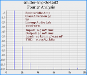
I have made one circuit idea New??? for Microphone Preamplfier, inverted with voltage gain.
And the input is fed to EMITTER of input transistpor (BC550C)
which is the heart of it all.
Should be possible to make some very nice, preamps / power amps
using this idea and develop and modify to suit requirements of the LOAD / OUTPUT.
====
You will not regret to read this post/design from October 2006
and the following posts where I attache a circuit/squarewave/fourier harmonics, from my own sim tests:
Amplifiers > Solid State > DIY Class-A mic-preamp
") Lineup Audio Lab - Emitter Microphone Amplifier
Lineup Audio Lab - Emitter Microphone Amplifier
http://www.diyaudio.com/forums/showthread.php?postid=1040210#post1040210
I attach Fourier Analys I like it !!
Shows some good things we can achieve when using this type of amplifier input & Idea.
In my Circuit the voltage gain is set x100 ... + 40dB
Which should be NOTICED / considered!
regars
to ya' all
This has been downloaded 9 time(s).
It is a bit like Jung Diamond buffer
The difference is what I like!
Input to EMITTERS of input pair in Complementary.
I have made one circuit idea New??? for Microphone Preamplfier, inverted with voltage gain.
And the input is fed to EMITTER of input transistpor (BC550C)
which is the heart of it all.
Should be possible to make some very nice, preamps / power amps
using this idea and develop and modify to suit requirements of the LOAD / OUTPUT.
====
You will not regret to read this post/design from October 2006
and the following posts where I attache a circuit/squarewave/fourier harmonics, from my own sim tests:
Amplifiers > Solid State > DIY Class-A mic-preamp
Lineup Audio Lab - Emitter Microphone Amplifier http://www.diyaudio.com/forums/showthread.php?postid=1040210#post1040210
I attach Fourier Analys
I like it !!Shows some good things we can achieve when using this type of amplifier input & Idea.
In my Circuit the voltage gain is set x100 ... + 40dB
Which should be NOTICED / considered!
regars
to ya' all
Attachments
OK, some important concepts have been missed:
The bootstraps are for voltage sake. The pseudo CCS function
is an irrelevant bonus. Irrelevant because emitter impedance
will STILL be low and irregular due to transistor or mosfet that
the collector must drive. The comparator transistor does not
add or remove any current from that equation, and neither
does a more perfect CCS.
Both ends of the bootstrap RC tie into nodes of the comparator
that are heavily error corrected in the voltage domain. Therefore,
this RC current source (or any other type) need not be linear of
its own accord. It only needs to be big enough in capacity to
handle the needs of the comparator at the lowest frequency.
Error correction is not a linear function. Linearity here is not an
issue. Constant current is not an issue. Low phase delay and
not running too low on bootstrap voltage are the only issues.
You are gonna need some buffer up front if you intend to drive
the output transistors. The comparators drop threshold voltage,
and amp error correction voltages, but do not "drive" anything...
They are in cascode with an input current that still has to be
actually driven from elsewhere.
A more perfect CCS does not make that requirement go away.
It only makes things needlessly complicated. Does it help input
emitter impedance somewhat? Yes, But only those leaks that
relate to CCS and/or bootstrap. Does it help input impedance
in regard to driving the output devices? Not at all.
A simple low impedance (perhaps diamond) buffer up front can
handle both drive requirements and fix both problems. To get
overly obsessed with CCS for pulling up or down comparators
will not.
Rant complete...
Regarding Paul's circuit... See that R9 in the upper CCS?
Tap your drive from the top end of that current sensing
resistor at the source node. Almost as-if a "Mu Follwer",
if you know that circuit from vacuum tubes... R9 still sees
only constant current across constant voltage, cascoded
back to the input emitters. But now, an amplified current
from the source is available to drive the output transistor.
Same thing on the bottom end, but JFET will need to be
complimentary..
Like Pass' Aleph, exact VGS-on matching of the JFET is
not a concern. The collector of the comparator will set
and correct for those thresholds. This is good.
If we're obsessed with having a good CCS AND having rail-rail output, then we should put the output devices and input circuitry on different rails.
The reason I put so much importance on making the Allison distortion-free is because if we do that, we can spend less time on the input circuitry, use less OLG, and have a stable circuit.
Currently the best solution I've come up with is to just use the standard two transistor CCS. It gives 1.3V dropout. But what I have in my latest schematic is fine with me. As Lineup said, the most he needs is around 10W. So I personally would be fine with the 20V limit. There is little improvement in distortion between what I already have and using a more specialized CCS.
I doubt there is much more that can be done with this circuit. Now is the point where I would personally be looking into MOSFETs and etcetera.
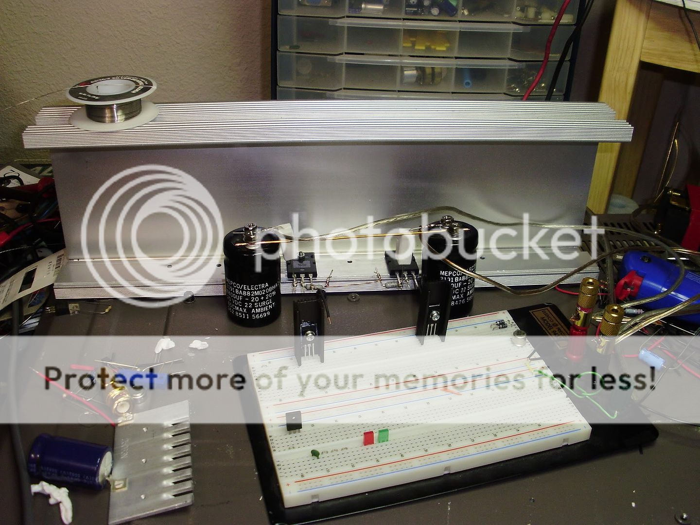
Paul, promise me that you'll post pictures when you get around to building your ideas.
I'm hoping to get a soldering kit sometime soon, so I might get around to cleaning the lead-free solder off of those leads and actually get something together. This will be the circuit I will build.
- keantoken
The reason I put so much importance on making the Allison distortion-free is because if we do that, we can spend less time on the input circuitry, use less OLG, and have a stable circuit.
Currently the best solution I've come up with is to just use the standard two transistor CCS. It gives 1.3V dropout. But what I have in my latest schematic is fine with me. As Lineup said, the most he needs is around 10W. So I personally would be fine with the 20V limit. There is little improvement in distortion between what I already have and using a more specialized CCS.
I doubt there is much more that can be done with this circuit. Now is the point where I would personally be looking into MOSFETs and etcetera.
Paul, promise me that you'll post pictures when you get around to building your ideas.
I'm hoping to get a soldering kit sometime soon, so I might get around to cleaning the lead-free solder off of those leads and actually get something together. This will be the circuit I will build.
- keantoken
Yes, that is what they say, 10 Watt Class A can be like 100 Watt Class AB, in quality.
Most speakers (SPL=90-95dB) only use an average level below or at 1 Wrms.
however we need to reproduce some peaks. 10 Watts RMS can make +10dB from 1 Watt.
Something in the area of 10-16 Watts. Not more.
In fact Nelson Pass has made a number of classical Class A
with output below 10Wrms.
Like 8 Watt from a power idle consumption of 100 Watt, is not unusual.
Now pass used single end, not push pull, so he is beliow efficiency of 10% on those Golden Oldie amplifier Pure Class A.
Not even some of the first www.firstwatt.com amps, F1, F2 etc.
have more than 8 true Wrms out .. in the peaks.
One question.
Do we really need the .22 emitter resistors?
I don't think beta difference is destructive to this circuit and there's no chance of thermal runaway. If the allison transistors heat up, the bias current actually lowers. The only reason I know of to keep these is so that a short circuit won't be so destructive... And even then we have fuses.
- keantoken
Hey, I finally got smart and bought some silver-bearing solder.
Then I sandpapered the tip of my butane iron. Since I already had used lead-free solder on the leads I decided to give it one more try so I wouldn't have to use lead-free and leaded solder on the same joint and tip.
My tragic flaw the first time was trying to solder the leads parallel instead of just wrapping one wire around the other. Needless to say it worked this time.
I'm going to build the rest of the circuit on my breadboard.
- keantoken

Hi do not forget my idea
use same driver/final devices on CFP
http://www.diyaudio.com/forums/showthread.php?s=&threadid=144681
use same driver/final devices on CFP
http://www.diyaudio.com/forums/showthread.php?s=&threadid=144681
And here is my turtle.
His name is squeegie, because he makes these funny squeeking noises
Try to modify that one, must be something you can do!
Or go read syn08 tpoic about John Curl low noise designs.
We only want the audible sound to be perfect!
lineup said:
Try to modify that one, must be something you can do!
Or go read syn08 tpoic about John Curl low noise designs.
We only want the audible sound to be perfect!
You miss the point! It is the flaws that give this one its musical character, not its advantages! This is the secret of Zen....
Oooooooooohhhhhhhhhhhmmmmmmmmmmmm.
I will do the best today to fix my soldering error and then will build the rest of the circuit on my breadboard.
Now that I'm doing it right, soldering is actually fun...
- keantoken
keantoken said:You miss the point!
It is the flaws that give this one its musical character
- keantoken
It is the flaws that give this one its musical character
Very good punchline .. even would fit as a one signature
There is much truth in this.
I would say imperfections in sound can give presens, bring life to a recording.
Like when we can actually hear singer breething in and sing out.
Ramoones & Sex Pistols
- could give rigid audiophiles the creeepy feeling until they faint,
but for real rock music lovers
they are an experience beyond the mediocre and streamlined bore, some productions of Sony Entertainment Corporation.
This should be played with HIGH VOLUME WATTS ...
The Ramones: Sheena Is A Punk Rocker
... and no fooking low noise, no fooking dammned audiophile fook amplifier speakers!
My Bottom ............ line:
More Punk & High Noise level .. and less of syn08 + Curl millimeter perfection will give you & me that true rocking punky feeling of being a dangerous rebellion/lineup

- Status
- This old topic is closed. If you want to reopen this topic, contact a moderator using the "Report Post" button.
- Home
- Amplifiers
- Solid State
- 50W, Class A, another one... :)