Beck,
I'm assuming you mean you want to change the amp from 117VAC (120) operation to 234VAC (240) operation, correct? For 117V operation you should have Black and Black/Red tied together BEFORE the thermistor and then Black/Yellow and Black/Green tied together BEFORE the other thermistor, does that look like what you have? If it does, now disconnect the Black/Red and the Black/Yellow and tie them together. The primaries were in parallel and now they are in series. That should do it. If you are not sure of what you are doing DON'T do it.
Craig
Craig, you're exactly right. I am trying to do this modification to not add a power limited converter in the loop.
I agree, there are 2 steps.
I have highlighted the first one in the document attched (Red Circle). The Black/White wire have to be unsoldered.
My concern is that I cannot find the other modifictation on this side. Can you confirm me that I have to access the alimentation Bloc upside ?
Regards,
Beck.
Attachments
Beck,
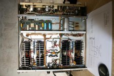
I think you are looking in the wrong place. To the right of the big silver can(capacitor) there are two little discs (thermistors) mounted on a terminal strip. The wires on that strip are the wires to the primary of the power transformer and the ones you need to work with. Do you see a Black, Black/Red, Black/Yellow, and Black/Green? Follow what I said in the first reply. If you are not sure DON'T do it.
Craig
the schematics I have posted is the recommandation from McIntosh.
I do not have the switch.
My concern, as you can see on the picture, there is neither Black/Yellow or Black/Green on the terminal switch near the Thermistor.... Could I have a model with only 1 primary and not 2 ?
also, you were talking about SN, and specially for number before and after 26M08. What is the difference ?
Beck,
The service manual I have is for amplifiers starting with 26M08, I don't know what was before that. There might even be a later manual than mine, I don't know. If you start with the power cord and follow it back you'll have to find all of the leads to the power transformer sooner or later. All of three of the transformer leads are cloth, should make it a little easier.
There is another MC2105 being worked on by Grant in a different post, maybe email him and ask him since he has one in front of him. If I had one in front of me I'd know what to do or be able to tell you where to look.
Craig
2105 source voltage
Bon jour, Msr. Beck!
Mon schéma n'a pas une date mai il à la mode pour serial #s avant de AH8376.
I have not attempted this conversion and my schematic doesn't show the switch referred to by Craig. His recommendation is correct but I also advise extreme caution before applying power.
I believe that Mcintosh has been consistent with their labels and particularly the cable colors. Are you sure that the power transformer is the original? You mentioned the possibility that you may have only one primary.
If you make the connections described by Craig you should be able to operate on 220v input
I've attached the diagram of the power supply from my copy of the Service Manual - hope this helps; tried to attach the entire file but received an error message from the Forums server that the file is too large !
All the best,
A bien tôt, Grant
To verify the transformer primary windings are serial
just occurred to me that the DC resistance of the primary windings should be twice the resistance of the primaries in parallel.
The resistance across the power cord in my MC 2105, which for sure is wired in parallel, is 2.8 ohms measured by my Fluke model 29.
The resistance across each of the thermistors is 2.5 ohms. So when the primary windings are arranged serially as accurately described by Craig, the resistance should be greater than 5.6 ohms, and probably even more.
Résumer :
parallel DC resistance at the power plug = 2.8 r
serial DC resistance at the power plug >= 2 x 2.8 r = 5.2r
hope that this helps if only just a little bit
à bientôt
Ho boys, I did not get noticied that some post have been added in my thread !
Sorry to not have given any sign of life.
I have started a thread also on a french forum and you can find some other pictures on it:
http://www.homecinema-fr.com/forum/viewtopic.php?f=1056&t=29912885&p=172814863#p172814863
They pointed the same finding that you did, llwhtt, about the REd Circle area, but I will post, tonight, a Zoomed picture thats shows off the wires we were looking for (BLK/YLW & BLK/GRN) nearby.
Thanks for your expert support,
Beck.
Re: To verify the transformer primary windings are serial
For me, the primary DC resistance will be x4 the parallel one, when serial.
We have 2 windings
each winding = X ohms
Parallel you will have RpDC = X/2 ohms
Serial you will have RsDC = 2 x X ohms
Then RsDC = 4 x RpDC
If we consider the thermistances : (2.5 ohms each)
RpDC = (X+2.5)/2 = X/2 + 1.4 = 2.8, then X/2 = 1.4, X = 2.8
RsDC = 2x(X+2.5) = 2X + 5.6 = 11.2, this is what we will measure after mod...
Philippe
grant_MH said:just occurred to me that the DC resistance of the primary windings should be twice the resistance of the primaries in parallel.
For me, the primary DC resistance will be x4 the parallel one, when serial.
We have 2 windings
each winding = X ohms
Parallel you will have RpDC = X/2 ohms
Serial you will have RsDC = 2 x X ohms
Then RsDC = 4 x RpDC
If we consider the thermistances : (2.5 ohms each)
RpDC = (X+2.5)/2 = X/2 + 1.4 = 2.8, then X/2 = 1.4, X = 2.8
RsDC = 2x(X+2.5) = 2X + 5.6 = 11.2, this is what we will measure after mod...
Philippe
parallel vs serial dc resistance on ppower transformer
Phillipe,
you are correct!
If Rs = x = dc resistance in parallel then the dc resistance of each primary coil is 2x = 2Rs and therefore the serial dc resistance is Rs = 2Rp = 2(2x) = 4x
merci beaucoup - thanks for the correction
Grant
Phillipe,
you are correct!
If Rs = x = dc resistance in parallel then the dc resistance of each primary coil is 2x = 2Rs and therefore the serial dc resistance is Rs = 2Rp = 2(2x) = 4x
merci beaucoup - thanks for the correction
Grant
- Status
- This old topic is closed. If you want to reopen this topic, contact a moderator using the "Report Post" button.
- Home
- Amplifiers
- Solid State
- Power Mod from 100V to 200V on MC2105