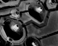
A friend gave me a Carver M-200t that abruptly quit working. "It was a great sounding amp until it quit. Dead quiet, no hiss, no 60 cycle hum." A quick look at the board revealed broken solder joints for very nearly every pin of every output device as well as a few others - easily corrected, and the amp came back to life. Mostly.
In addition to whatever signal put through it, it now has a subtle 60 cycle hum and some very apparent "dirty" hiss.
I've been in touch with Anatech, resident Carver specialist, and we've just gotten started. From our first few e-mails:
If you don't have the service manual handy, you can find it here:
http://thecarversite.com/manuals/files/Carver M-200t service manual .pdf
You may need to register (painless) at that site to view the .pdf.
I'd hate to think of killing any decent amp through inexperienced tinkering, but these are at least relatively common and I have nothing but a little time and $15 invested in it at preset. In other words, no harm if the whole thing goes south. The PS caps and most of the other electrolytics are on my bench ready to go. Best to wait for some diagnostic work first? I'll start a thread on diyaudio as we get rolling...
The high rail was +/- 44 volts.
I doubted my ability to get any deoxit into the voltage adjust trimpot, so I just worked it back and forth a bunch, reset it, then adjusted with the amp on to get the high rails to +/- 55. The other two are +/- 24.8 and +/- 15.7.
-----------------------------------------------------
The last dabbler to open this amp lifted one of the traces to the triac and effected a somewhat clumsy repair with a bit of wire. Also, space on the board for "TR1" is empty - there is only "TR2", never mentioned in the manual. I assume it's from a running change in production.... ?
So here we go. If anybody else has advice or suggestions, I'd be glad to hear them.
Anatech, many thanks for your help!
In addition to whatever signal put through it, it now has a subtle 60 cycle hum and some very apparent "dirty" hiss.
I've been in touch with Anatech, resident Carver specialist, and we've just gotten started. From our first few e-mails:
Thanks for getting back to me. I have everything at my (not quite immediate) disposal except the variac and distortion analyzer. I'm a good hand at de/soldering, but a novice when it comes to diagnostics. However, I think you'll find me a quick study.The first thing I suspect is oscillation if you are hearing a hiss.
In order for your attempt to service this to have any chance of success,
you will need an oscilloscope, good meter, signal generator, good
soldering station (not an iron only) and a variac. These would be the
minimum requirements. A distortion analyzer wouldn't hurt either.
Experience would be a must as well. These are not simple amplifiers to
service and my experience with the average service technician is that
they really don't understand how a normal amplifier works. Not really.
Let me know what you have on hand for equipment please, and some
idea of your experience in servicing audio amplifiers. That will give
me a good idea what to expect.
If you don't have the service manual handy, you can find it here:
http://thecarversite.com/manuals/files/Carver M-200t service manual .pdf
You may need to register (painless) at that site to view the .pdf.
I'd hate to think of killing any decent amp through inexperienced tinkering, but these are at least relatively common and I have nothing but a little time and $15 invested in it at preset. In other words, no harm if the whole thing goes south. The PS caps and most of the other electrolytics are on my bench ready to go. Best to wait for some diagnostic work first? I'll start a thread on diyaudio as we get rolling...
The triac is not shorted, although its heatsink wasn't making contact...last dabbler to open this amp left it loose. New compound and screws are tightened.Well, that sounds good then. The very first thing you need to do is make sure the triac (TR1) is not shorted. This little fellow only has two supply tiers, one at 25 VDC and the other at 55 VDC. These are bipolar. You also have an op amp supply running at 12 VDC bipolar. Make sure your 55 V supply is correct before you do anything else, assuming that the triac is not shorted. If you do find a blown triac, do not apply power! You must replace this part before attempting to power up the amplifier. The voltage adjust control (in the power supply schematic) may be oxidized. Either clean it for now, or replace it with the same type of control.
Let's see where you end up with this information
The high rail was +/- 44 volts.
I doubted my ability to get any deoxit into the voltage adjust trimpot, so I just worked it back and forth a bunch, reset it, then adjusted with the amp on to get the high rails to +/- 55. The other two are +/- 24.8 and +/- 15.7.
-----------------------------------------------------
The last dabbler to open this amp lifted one of the traces to the triac and effected a somewhat clumsy repair with a bit of wire. Also, space on the board for "TR1" is empty - there is only "TR2", never mentioned in the manual. I assume it's from a running change in production.... ?
So here we go. If anybody else has advice or suggestions, I'd be glad to hear them.
Anatech, many thanks for your help!

A minor update...
I recapped the amp with Nichicon audio-grade electrolytics. Admittedly, I only gave the schematic a cursory look as to specific application for the caps in question, but assumed the KW would be alright for my purpose. No excitement after a double-check and power up. Rail voltages and bias were set according the the service manual's instructions.
Without an input connected, the 60 (or 120?) cycle buzz remains and matches the buzz coming from the 'magnetic power' transformer. With an input connected, the buzz and most all of the 'dirt' go away, but the hiss remains. The amp does pass a signal and sounds pretty good - albeit through a pair of Minimus 7 speakers.
Putting the 'scope probe at the junction of T2's secondaries and their corresponding rectifier diodes shows (to me) an odd-looking waveform. The AC comes in big, steep spikes that alternate with little spikes of the same shape. Anybody know if this is typical output for a Carver transformer in this setup?
Thanks for the though, ACD.")
I recapped the amp with Nichicon audio-grade electrolytics. Admittedly, I only gave the schematic a cursory look as to specific application for the caps in question, but assumed the KW would be alright for my purpose. No excitement after a double-check and power up. Rail voltages and bias were set according the the service manual's instructions.
Without an input connected, the 60 (or 120?) cycle buzz remains and matches the buzz coming from the 'magnetic power' transformer. With an input connected, the buzz and most all of the 'dirt' go away, but the hiss remains. The amp does pass a signal and sounds pretty good - albeit through a pair of Minimus 7 speakers.
Putting the 'scope probe at the junction of T2's secondaries and their corresponding rectifier diodes shows (to me) an odd-looking waveform. The AC comes in big, steep spikes that alternate with little spikes of the same shape. Anybody know if this is typical output for a Carver transformer in this setup?
Thanks for the though, ACD.
carver repair
No disrespect to Anatech, he is awesome, but to avoid using up all his time, you can go to the CarverSite and register. Post on the repair thread and you will get expert advice.
The person that runs it knows this amp backwards, forwards and upside down. He is helping me fix a carver of mine.
No disrespect to Anatech, he is awesome, but to avoid using up all his time, you can go to the CarverSite and register. Post on the repair thread and you will get expert advice.
The person that runs it knows this amp backwards, forwards and upside down. He is helping me fix a carver of mine.
Looks like the amp is good to go, with nothing notably unusual going on. Many thanks to Anatech again for his assistance, and thank you also to lgreen for the suggestion. Here are Anatech's most recent words, to wrap up the thread and hope that it'll help somebody else searching the forums someday...
What you are seeing is somewhat normal with Carver amps. With the inputs open, you have a a very high impedance condition. All noise will be picked up and the supply generates a lot of noise. Check the amp to see if it's oscillating with the inputs open or shorted (could be your hiss sound).
The waveforms are going to be "odd" on the power supply, especially the transformer windings. Remember, this is a special transformer that operates more on current. The unloaded condition may cause the triac to skip firing sometimes. Not unlike a race engine idling, they run like crap at idle but wake up and run nicely under power. I wouldn't expect you to have any trouble with the job you just performed unless you made a big mistake. Good show.
These amps are pretty stable. Most problems you run into are due to the waveform the capacitors have to charge on, and some overheated components. Just use your eyes. Amps on the road will all develop bad solder connections. Fan motors (if equipped) need lubrication or replacement (if they weren't). Fan blades can sometimes snap off, but that is probably an induced fault. Blowing out the dust is normal with any amp.
Check resistor values if they run warm. Sometimes the supply sensing resistors will change value. Like values ought to be matched to at least a rough degree.
Rather than a new thread, I'll just add to this one
Hiyas guys...
A friend asked me to take a look at his 200T amp - he was getting no output at all.
I'm pretty much an amatuer at this, but do have electronics training and a decent bench downstairs with meters, scope, nice iron, signal gen, DBT.
Briefly tested, yup, no output.
Came here, read up on it a little, downloaded the crappy schematic from this thread. Didn't find a better one for free.
A close look at solder joints showed several cracked on the outputs. Here's my photoshop-enhanced photo with cheap camera of an example.
I got out the big iron to fix these up, ended up removing most of the old solder and then I put new on.
My PC is acting up, I'll be back.
Attachments
- Status
- This old topic is closed. If you want to reopen this topic, contact a moderator using the "Report Post" button.
- Home
- Amplifiers
- Solid State
- A sick Carver M-200t gets medicated