Hello everyone.
I search for description or any info about Yamaha so-called 'Hyperbolic Conversion Amplification'.
Maybe one of you knows something about this circuit or know an article, US patent or any type of info about the circuit.
I search for description or any info about Yamaha so-called 'Hyperbolic Conversion Amplification'.
Maybe one of you knows something about this circuit or know an article, US patent or any type of info about the circuit.
Last edited:
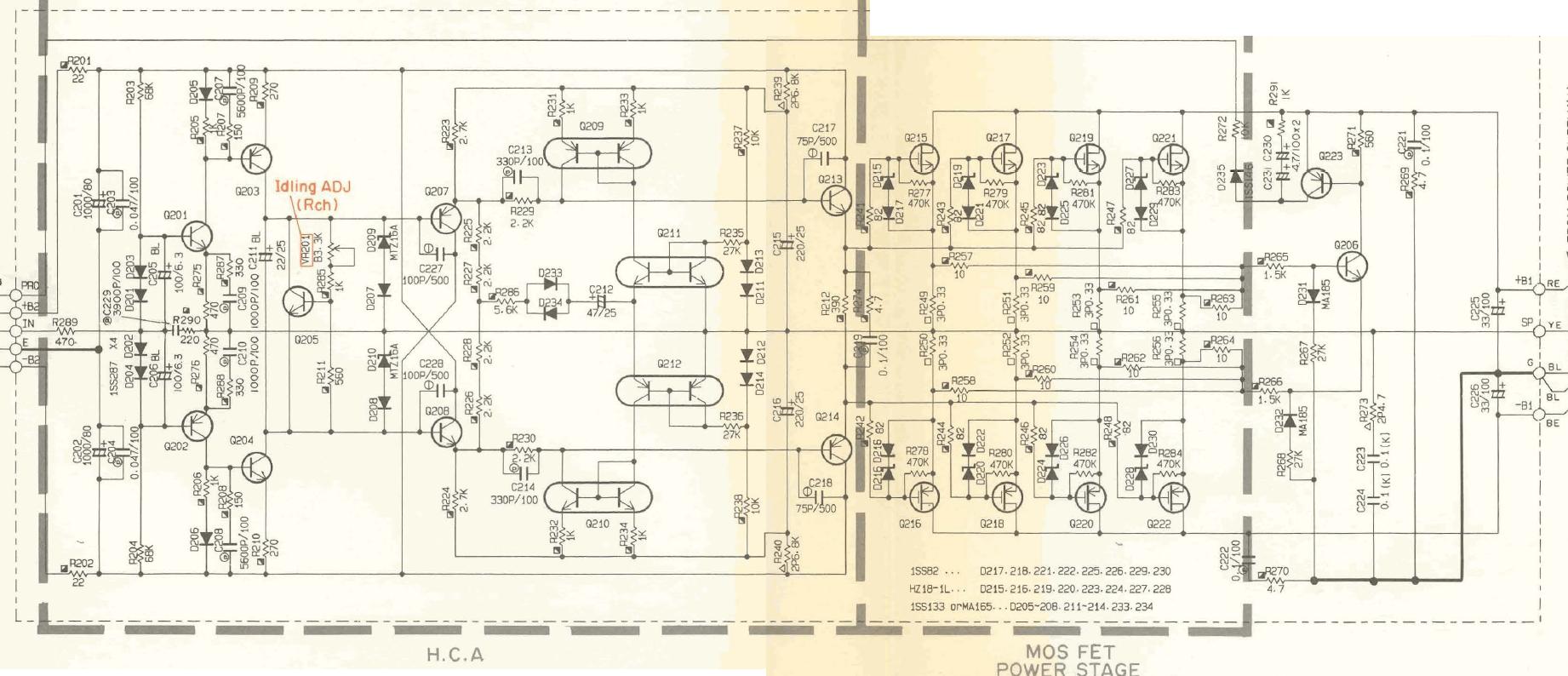
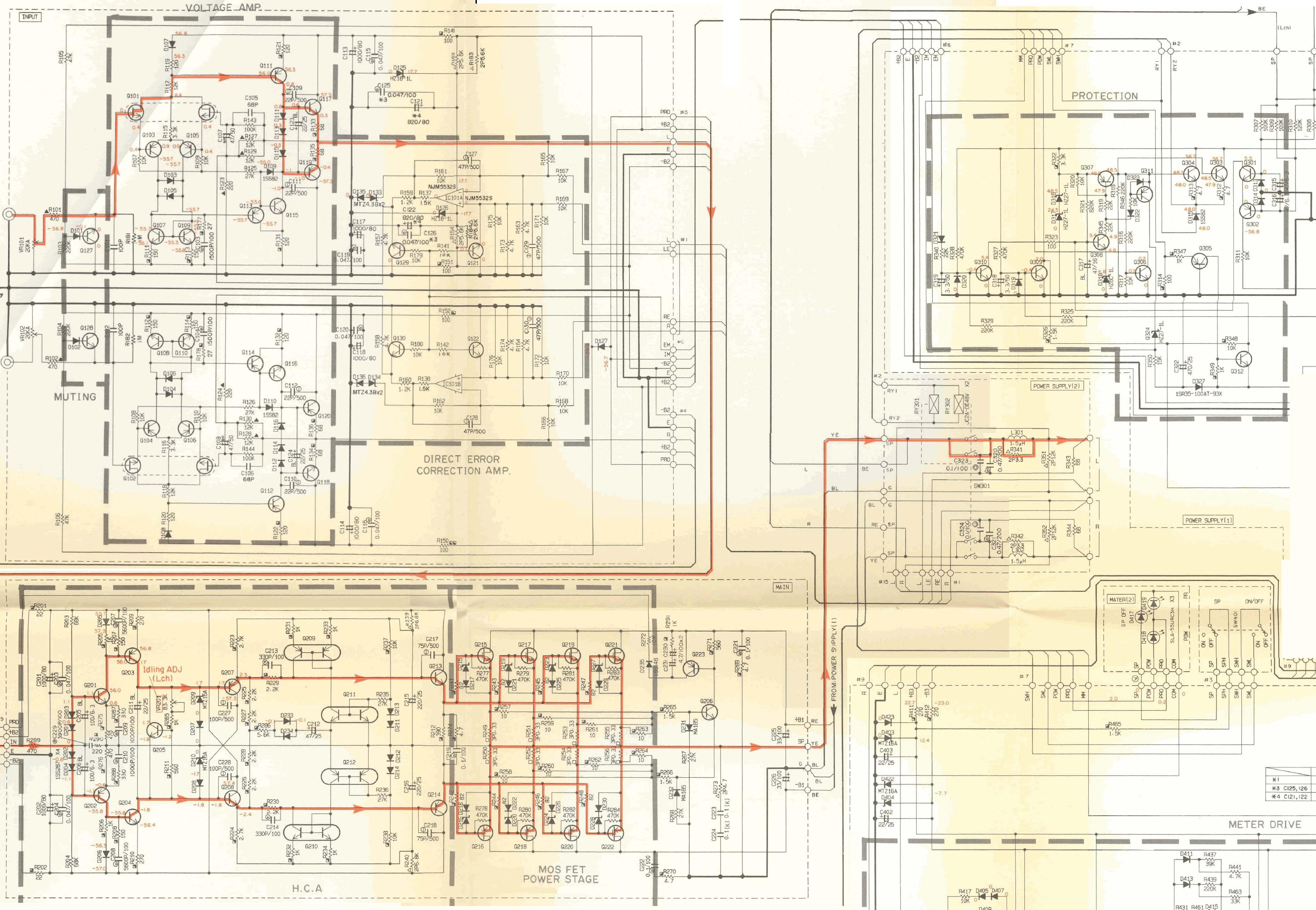
It doesn't look too complicated. Q201/202 are what's commonly called a "current feedback" input stage, where the inverting input is a low impedance node. These have high slew rate because they operate in class AB, but DC offset is hard to control.
Then Q203/204 are an ordinary complementary VAS.
The next bit is more interesting. The four transistors Q207/208/213/214 are connected as a "diamond buffer", which is just an emitter-follower where the bias voltage is provided by a pair of common-emitter transistors. However, Q213/214 are also drivers for the output MOSFETs, thus there is the Vbe multiplier further back with Q205 instead of the usual diamond buffer which would have the bases of Q207/208 directly connected together.
The four current mirrors just provide the constant currents needed to bias Q207/208, and they also provide short-circuit protection via the two diodes D233/234 (if the output voltage differs from the VAS output voltage by more than ~0.6V then the diodes turn on, removing drive to the output stage).
I don't know where the "Hyperbolic Conversion" comes into it, if that even means anything.
EDIT: I see there is also a bootstrap provided by C215/216. I don't know why they have bothered to put that in when they already have a separate supply voltage for the MOSFETs.
Something tells me those current mirrors are going to reduce distortion, making this somewhat of a non switching circuit, I have seen similar russian designs, how old is this amp circuit???
I have Yamaha AX-930 (HCA BA3122N ).
HCA use in Yamaha AX-730. AX-1050.AX-1070.AX-1090.MX-2.
MX-630 ...
HCA use in Yamaha AX-730. AX-1050.AX-1070.AX-1090.MX-2.
MX-630 ...
This HCA circuit is a part-of the Yamacha MX-2000 (1988) amplifier schematics.

http://www.electricalhobby.com/images/yamaha_mx10000_ext1.jpg
And the later version of HCA circuit was a IC BA3122N
PS homemodder can you post the schematics of this Russian designs
http://www.electricalhobby.com/images/yamaha_mx10000_ext1.jpg
And the later version of HCA circuit was a IC BA3122N
PS homemodder can you post the schematics of this Russian designs
Attachments

Sorry, It was on some russian site and I stumbled upon it I cannot even remember how, I do not speak russian but had a immigrant here translate it for me, its not the exact circuit but it looks to me its the same principle, Ill have a look if I maybe saved a page from the site like I usually do when I find something interesting, and russian designs are.
check out this thread:Hello everyone.
I search for description or any info about Yamaha so-called 'Hyperbolic Conversion Amplification'.
Maybe one of you knows something about this circuit or know an article, US patent or any type of info about the circuit.


Yamaha's Hyperbolic Conversion Amplification (HCA) Circuit
Hello, I'am looking for an IC called BA3122N used in YAMAHA MX-2.
Does anybody know where this special IC can be found. I tried several on-line sites but it seems to be difficult. Also another question, does one know how this circuit works and can be build with discreet components? Thanks in advance for the comments.
Does anybody know where this special IC can be found. I tried several on-line sites but it seems to be difficult. Also another question, does one know how this circuit works and can be build with discreet components? Thanks in advance for the comments.
You will likely only get a working IC from an old unit.
Many earlier HCA amps implemented this in a discrete circuit, current mirrors will not be as well matched. I have cloned this design and built it (posted on here in another thread) - no way to compare it to an original amp with discrete or IC HCA section, but it's a direct copy of the Yamaha design, so if it worked before it would work again.
So yes, Yamaha built it with discrete components, so it is possible.
Last edited:
Has anyone successfully built discrete HCA as a direct replacement for BA3122N?
I've got an AX-1090 with one channel blown, BA did not survive.
I've got an AX-1090 with one channel blown, BA did not survive.
It's a really unique way of achieving the crossover distortion cancelling benefits of class-A bias without as much waste heat. Some companies used sliding bias, or a ringing circuit that would ramp up the bias and die down when there was less power demand.Hello everyone.
I search for description or any info about Yamaha so-called 'Hyperbolic Conversion Amplification'.
Maybe one of you knows something about this circuit or know an article, US patent or any type of info about the circuit.
Yamaha's bias was different was different in the MX-2000. The biasing circuit listens to the incoming signal and modulates in class-C at the zero crossing point. In the earlier models the B+/- was also stepped up or down depending on power demands. Class H, class C, class A.
Last edited:
- Home
- Amplifiers
- Solid State
- Yamaha HCA circuit