I have noticed that long tail pairs tend to be nonlinear because the current input at the emitters changes when the voltage at them changes with the input and feedback audio. The normal fix is to supply constant current to the emitters instead of using a single resistor. The constant current source is a clean solution distortion-wise.
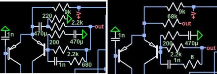
I believe that I have discovered that there might be a remedy which is an alternative to a constant current source. Connect a suitably-valued a resistor from the audio output to the emitters of the long tail pair. Such a resistor cancels out voltage changes.
I doubt that I am the first to notice this solution. I would be interested to see who else has tried it and what the result seemed to be.
Alternately, there should be circuits where constant or near constant current is not desirable. Then connect an extra resistor and capacitor similar to a normal feedback network, but to the emitters of that LTP in addition to the one at the base of the feedback transistor. Another difference is that the capacitor and gain resistor are switched in position. Consider it as a type of bootstrapping. Like standard bootstrapping, it should increase the impedance at the base of the input transistor.
These are my observations. I will see what thoughts other people have.
Attachments
AndrewT said:was it the Patchwork that used this bootstrap in it's sims to generate that cancellation effect?
Hi Andrew. I was playing around with the idea on a circuit I have been designing in LTspice. I am working on the simplest class D amplifier that I can come up with that uses discrete components, only N-ch MOSFETs, and operates on at least +/-40vDC.
Improved LTP Linearizer
Hello.
I have a new long tail pair linearizer. It offers a simple alternative to constant current sources. It looks different than other things that I have seen, but I doubt that it hasn't been tried before by someone else.
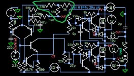
I selected the three resistor values which replaced the original 39k resistor by first setting the sum of the ones in series with the B+ equal to that 39k one. 36k + 3k = 39k. Then I used LTspice to find the third value by trial and error. That 56k resistor maintains almost constant current through the 36k one.
Hello.
I have a new long tail pair linearizer. It offers a simple alternative to constant current sources. It looks different than other things that I have seen, but I doubt that it hasn't been tried before by someone else.
I selected the three resistor values which replaced the original 39k resistor by first setting the sum of the ones in series with the B+ equal to that 39k one. 36k + 3k = 39k. Then I used LTspice to find the third value by trial and error. That 56k resistor maintains almost constant current through the 36k one.
Attachments
darkfenriz said:Current source is still much better PSRR-wise
I agree about the PSRR. If the power supply changes, this type of current source goes up or down with the voltage. However, it is in a linear manner because this circuit offers a more linear input impedance compared to a more ideal constant current source.
homemodder said:Ive played a bit with these resitor current sources, try bootstrapping a active current source, this has benefits compared to standard one.
The latest example that I showed is close to a type of bootstrapping. If I added a capacitor in series with the 56k resistor, it would be. In order to make this project easy to assemble with p2p and very compact without SMD parts, which I always avoid, I've omitted the capacitor. it isn't really much needed since the voltage on the emitters of the long tail pair is only nominally offset by .7v above the output voltage.
I was seeking a lessening of the fluctuating of the input impedance within an audio cycle. I wanted to make operation of the circuit more like inputing the audio signal at the inverting input, but without the loss of input impedance that you get at the non-inverting input.
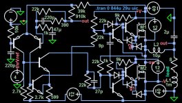
I have now used the simulator to confirm that a single resistor will do the job. So, I went back to using the original 39k resistor and was able to determine the optimal value of the linearizing resistor to be 910k, placed between the amplifier output and the emitters of the LTP.
Calculate it by multiplying the amplifier gain by the value of the current resistor and then go up to the next higher value. You want the normal feedback divider at the base of the feedback transistor to be the dominant actor in the circuit.
I confirmed the 910k value by temporarily adding a 1ohm resistor in series with the emitters of the LTP and using simulation to measure its current. I have not shown the 1ohm resistor in the next diagram.
I should mention that this amplifier is still being refined. If I build an amplifier this one presently is one of my favorite possibilities.
Attachments
I think this is a great idea....If one's to use a seperate supply for the the front end and VAS stage of the amplifer the need for high PSRR i not really there... Then this could indeed be a very good way to balance the LTP....I don't fancy the CAP,...as is will ad sonic signature... If the Pair was Jfets it wouldn't be needed at all...I suspect..
MiiB said:I think this is a great idea....If one's to use a seperate supply for the the front end and VAS stage of the amplifer the need for high PSRR i not really there... Then this could indeed be a very good way to balance the LTP....I don't fancy the CAP,...as is will ad sonic signature... If the Pair was Jfets it wouldn't be needed at all...I suspect..
Thanks. I figured that if a separate power supply made the voltage for the low power part more stable, some of the benefit of the stable current between half cycles would be lost, but the benefit is that the current would be much more constant over the long term.
The effect of not having the capacitor would translate to .7/B+ * offset voltage without the linearizer. That should be a negligible figure.
My impression is that a capacitor, if chosen with a high enough value so as to not be nonlinear inside the audible frequency range, would not be much of a problem because it is within the feedback loop.
Hi
That is an interesting way of manipulating the input pair, modulating the input tail current wrt the output voltage. I haven't tried that before. What I have tried is modulating the tail current wrt the VAS common mode bias current. Thinking of the input stage and VAS as a single entity, I used a fixed CCS for the VAS and its mirror, and a CMFB loop to adjust the tail current to always maintain a fixed common mode bias in the VAS. What I like is that it works in a symmetrical topology too and reduces the effects of having a slightly dynamically mis-matched input pair. (J-fet's ) But I love J-fet’s so, and am unwilling to fork over such a high stack for matched pairs. The amp I made like as this on vero-board 2 years ago still works perfectly.
That is an interesting way of manipulating the input pair, modulating the input tail current wrt the output voltage. I haven't tried that before. What I have tried is modulating the tail current wrt the VAS common mode bias current. Thinking of the input stage and VAS as a single entity, I used a fixed CCS for the VAS and its mirror, and a CMFB loop to adjust the tail current to always maintain a fixed common mode bias in the VAS. What I like is that it works in a symmetrical topology too and reduces the effects of having a slightly dynamically mis-matched input pair. (J-fet's
) But I love J-fet’s so, and am unwilling to fork over such a high stack for matched pairs. The amp I made like as this on vero-board 2 years ago still works perfectly.My impression is that a capacitor, if chosen with a high enough value so as to not be nonlinear inside the audible frequency range, would not be much of a problem because it is within the feedback loop.
I don't think it is so much the value of the cap but rather the material it is made of, wrt non-linearities, DA, ect.
CBS240 said:Hi
That is an interesting way of manipulating the input pair, modulating the input tail current wrt the output voltage. I haven't tried that before. What I have tried is modulating the tail current wrt the VAS common mode bias current. Thinking of the input stage and VAS as a single entity, I used a fixed CCS for the VAS and its mirror, and a CMFB loop to adjust the tail current to always maintain a fixed common mode bias in the VAS. What I like is that it works in a symmetrical topology too and reduces the effects of having a slightly dynamically mis-matched input pair. (J-fet's
Your project seems pretty cool. I can see some advantages to using j-fets.
CBS240 said:
I don't think it is so much the value of the cap but rather the material it is made of, wrt non-linearities, DA, ect.
People say how they can hear differences in capacitors. The location in the circuit would be a big factor. If the capacitor's value is not causing filtering, then if it is in series with such a large value resistor like in the tail current compensating circuit, I don't think the small impedance irregularities due to the construction of the capacitor would matter much.
Electrone said:
I believe that I have discovered that there might be a remedy which is an alternative to a constant current source. Connect a suitably-valued a resistor from the audio output to the emitters of the long tail pair. Such a resistor cancels out voltage changes.
I doubt that I am the first to notice this solution. I would be interested to see who else has tried it and what the result seemed to be.
Leo Fender used it long time ago in his tube amps.
CBS240 said:Hi
That is an interesting way of manipulating the input pair, modulating the input tail current wrt the output voltage. I haven't tried that before. What I have tried is modulating the tail current wrt the VAS common mode bias current. Thinking of the input stage and VAS as a single entity, I used a fixed CCS for the VAS and its mirror, and a CMFB loop to adjust the tail current to always maintain a fixed common mode bias in the VAS. What I like is that it works in a symmetrical topology too and reduces the effects of having a slightly dynamically mis-matched input pair. (J-fet's
The next step would be to discard the second (inverting input) transistor from the pair and get better (in terms of audio) linearity, higher slew rate, and wider frequency band. It may be viewed as an emitter follower for the negative feedback signal. If output resistance of your amp is low, do you need an emitter follower?
Re: Re: Long Tail Pair Linearizer
Cool. I thought that someone else must have tried it. I know that tube circuit designers tried a lot of things to get the most out of a circuit.
Wavebourn said:
Leo Fender used it long time ago in his tube amps.
Cool. I thought that someone else must have tried it. I know that tube circuit designers tried a lot of things to get the most out of a circuit.
AKSA said:Electrone,
You should build this design, and see how it sounds.
It will change the profile of the distortion, and with the additional H2/H3 mask the higher order distortions produced by the highly non-linear VAS, crossover, and the fb loop.
Hugh
I plan to incorporate the single resistor method in a future project, if I get the chance. Alas, I'm not the best sound critic with my tin ears. Hugh, thanks for the encouraging comment!
- Status
- This old topic is closed. If you want to reopen this topic, contact a moderator using the "Report Post" button.
- Home
- Amplifiers
- Solid State
- Long Tail Pair Linearizer