Nelson Pass has inspired me when he said there
is no limit on how many output stage mosfet
transistors you can parallel provided that you
can drive them
The squirrel cage in my head is turning, wondering
if using 25 - 50 output mosfets per rail is
doable with the attached schematic (av800).
I guess 25 per rail is good enough ... The design
has been built by Holton with 10 per rail, but
the crazy rabid fans of high powered amplifiers
need a "fix" and want more like a junky seeking
the next needle.
Why ?
Because.........
1. The muscle car fanatics know what I'm taking
about. Need for speed and engine rumbling.
2. It would be cool to drive the new breed of super
monster X-max woofers, typically DVC of 1 ohm
parallel the woofer coils for 0.5 ohm load with
a classic AB design, not the class D designs chosen
today by many.
How? Beats me, if I knew, I wouldn't be posting here.
Can the buffer stage (Q4, Q5) which is IRF610 and IRFP610
be replaced with IRFP240 and IRFP9240 and R9 be lowered
to give me more drive for the beefy output stage of
25 transistors per rail ?
Drools.....
Researching the archives revealed that Nelson was
gonna throw us a bone and give the fans a monster
AB design, a gleam in his eye...
Patiently awaits
Oh please
Attachments
Hi,
for drivers, You can use IRF630/9630, because they are much more linear than IRFP240/9240.
But I think this idea is good if You have a lot of money, or You are the sponsor of the local electronic shop.
If the amplifier works with 10pairs, why do You wan to use 50 of them?
If You have 100m of heatsinks, You can build 1000W class "A" amplifier...
Sajti
The 10 pair version is only rated no less than 4 ohms continuous
at 1kw. I read some posts that said it's able to do 1600w
short term into 2 ohms.
http://www.aussieamplifiers.com/1kwamp.htm
But, it would be nice to drive those new 0.5 ohm woofers
at high power. Some of those woofers have 1-2kw power
ratings.
P.S. What happened to diy member "Kilowatt" ?
I read all his posts about his desire to build the
7200w amp running of the AC mains.
Thinks....
Scratches head....
Stares at wall .....
If you configure those buffer
mosfet (pre-output stage), ie,
IRF610 or whatever, you are
subject to the T0-220AB package heat
dissipation of 50W ? So, finding
a higher current rated transistor
in the same package might not
help you ?
True?
False?
I don't see said the blind man
If you're in the mood of matching 50+ transistors (that will be one hell of a job and you'd have to buy hordes of them), why not build a normal powered amp with massively paralleled smaller devices, like irf 620s, 630s, 520s, 530s etc (or even more smaller devices)? That'd be interesting so see.
Sounds like fun, matching hundreds
of fets, time to make a transistor
matching tester (hehe)....
Actually, I saw a post on the subject
in the archives, but the link was
broken to the schematic (doh!)...
Trying to figure something out....
If you have two transistors in
the output stage that are perfectly
matched, then you don't need
the source resistor because current
sharing is equal.....
But, in reality it's not the case
so most people use 0.1 - 0.3 ohms.
Question is;
Take the same 2 transistors
and add 8 more in parallel,
unmatched.
If you are driving the same current
thru 10 transistors as you did
with 2 transistors, would not
the current split thru 10 transistor
paths instead of two ? Would this
not but a less of a burden on
the whole bank of 10 vs. 2 ?
(but if you increase current, that's
another story , heh)...
Is this right or wrong assumption?
Example,
If I drive 2 amperes thru the output
stage of two matched transistors,
1 ampere passes thru each one.
If I drive 2 amperes thru the
output stage of 10 unmatched
transistors *and* let say
one of those transistors is the
current hog and allows 1 ampere
to pass, then the other ampere
of current splits into the other 9
transistors, in which case, the
unmatched bank would still work?
FYI, I plan to match, but still
wonder.......
The source resistor not only for the current matching!
If You check some small power amplifier, with only one pair of output device, You can find source resistor too. Why? This resistor helps to the bias network, to keep the bias constant over different temperatures.
It also separates the emitter followers from capacitive loads, which can results oscillation.
Sajti
50 ways
Sajti is absolutely right. I would add that if you increase the # of devices, you can increase the source resistors. For say 25 devices you can use 2 Ohms and still have an equivalent source resistor of 80 milliOhms or something like that. But because each sees 2 Ohms, matching is unnecessary.
Jan Didden
Yes, exactlythylantyr said:Nelson Pass has inspired me when he said there
is no limit on how many output stage mosfet
transistors you can parallel provided that you
can drive them

Driving many pairs is hard because the gate-drain capacitance will get huge eventually which means highly capacitive load for the poor driver stage.
Why don't you start in the other end? Max stort term continous current, min practical load => minumum amount of pairs.
Bear in mind that wiring becomes very important if you have many pairs.
...but it's cool to have many transistors, impresses your mates

Cool information.
Taking notes.
Thanks.
I'm laying out the proven 20 output
transistor design right now.. I will
probably make different flavors
of PCB to accomodate the madness..
When layout is done, I will make
the crazy version and order some
pcb's so I can do some smoke tests
Taking notes.
Thanks.
I'm laying out the proven 20 output
transistor design right now.. I will
probably make different flavors
of PCB to accomodate the madness..
When layout is done, I will make
the crazy version and order some
pcb's so I can do some smoke tests
Re: Re: 50 Output Stage Transistors?
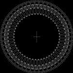
Take a leaf from the book of aero engine designers of yesteryear. Lay the fets out radially in two circles, all the upper fets in one circle and all the lower ones in another circle. Sort of like two paddle wheels. Have all the leads point toward the centre. This will give you the lowest resistance, lowest inductance and shortest lead length possible, with no fet out on the end of a conductor but rather equal conductor length to all.peranders said:Bear in mind that wiring becomes very important if you have many pairs.
another factor to consider is the positive coefficient for Rds vs. temperature. If one mosfet is taking on increasing load, its temperature will go up, causing its Rds to go up as well, which in turn reduces the load on that mosfet.
I have used one pair of 540/9540 without the source resistors and no apparent ill effect.
I have used one pair of 540/9540 without the source resistors and no apparent ill effect.
That effect is really only most apparent when the fets are fully switched on, like when used in a switching power supply etc. For linear use, the gate threshold has a *negative* tempco of typically -5.5 mV / deg C which has a much greater effect than Rds variation. So for a fixed bias voltage and linear usage, the hottest fet is going to turn on further than the rest.millwood said:another factor to consider is the positive coefficient for Rds vs. temperature. If one mosfet is taking on increasing load, its temperature will go up, causing its Rds to go up as well, which in turn reduces the load on that mosfet.
P.S. Hexfet type mosfets at least. e.g. IRFxxx types. Not sure about lateral fets.
Re: Re: Re: 50 Output Stage Transistors?
14" PCB.
Cool.
Circlotron said:
Take a leaf from the book of aero engine designers of yesteryear. Lay the fets out radially in two circles, all the upper fets in one circle and all the lower ones in another circle. Sort of like two paddle wheels. Have all the leads point toward the centre. This will give you the lowest resistance, lowest inductance and shortest lead length possible, with no fet out on the end of a conductor but rather equal conductor length to all.
14" PCB.
Cool.
Attachments
A big circle like that would work well for hooking up the FETs, but what about heat dissipation? You might want to think about that, I'm guessing you'll be using huge heatsinks, since you've got that much power, so you might want to spread out the heat sources a little more. Might think of a larger circle, or maybe several smaller circles spaced out. Otherwise you might have to end up using a larger heatsink to combat the inefficiency of how you mounted your fets.
JoeBob said:A big circle like that would work well for hooking up the FETs, but what about heat dissipation? You might want to think about that, I'm guessing you'll be using huge heatsinks, since you've got that much power, so you might want to spread out the heat sources a little more. Might think of a larger circle, or maybe several smaller circles spaced out. Otherwise you might have to end up using a larger heatsink to combat the inefficiency of how you mounted your fets.
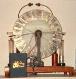
Why not put a small individual heat sink on each FET and use a motor to spin the whole PCB? Use ring shaped tracks and brushes to get power into and signals in and out of the board. I can see it now, this could be like one of those crazy lightning machines from an old Frankenstein movie! "It's Alive... ALIVE!!"
Better go take my meds...
Phil
Attachments
- Status
- This old topic is closed. If you want to reopen this topic, contact a moderator using the "Report Post" button.
- Home
- Amplifiers
- Solid State
- 50 Output Stage Transistors?