Listen...but please, use a very good speaker and amplifier (not the small computer trash boxes)
Increase your volume and enjoy...sorry the image quality.
Amplifier descriptions, schematics and all stuff will come soon.
http://www.youtube.com/watch?v=w3QphsVZm0Q
Carlos
Increase your volume and enjoy...sorry the image quality.
Amplifier descriptions, schematics and all stuff will come soon.
http://www.youtube.com/watch?v=w3QphsVZm0Q
Carlos
Attachments
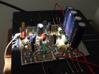
Trust is an old style amplifier, having the awfull condenser into the output....
... a scandalous thing to many forum folks..sorry because of that.
It is not high power, as it is an old style amplifier..something based into the sixties and seventies amplifiers.... does not use differential amplifier.... very simple, also no symetrical supply.
I was trying it those last days...friends came to evaluate, also children...they felt them coloured but delicious and pleasant sound..the same i have perceived.
Power is not more than 20 watts into 4 ohms and 10 or 12 watts into 8 ohms... this can increase if you use 70 volts non symetrical power supply (Dx supply modified to give you 70 Volts instead of 35 plus 35 volts)...and them power about 70 to 100 watts will be possible.... just will be needed to adjust the input transistor base resistances and to re-adjust the bias trimpot.
It is working class AB..and very low biased.. output emitter resistances are draining some miliamperes only (5 to 15 miliamperes)... frequency response is awsome and simulator results are excelent.
Enjoy a new Dx Amplifier...this one, the Trust, is a delicious amplifier.
Has an advantage...if you have burned parts because some accident, or continuous overload...the speakers will not be damaged, because the output electrolitic condensers are there to block any DC to the speaker.
regards,
Carlos
Attachments
I have just tuned the amplifier for sonics
and in advance to give you the schematic i need to observe what happened into the simulator with my modifications... sonically i know..but i want to know about numbers too.
Soon i will give you complete PDF schematic.
For a while, listen the youtube video and watch this simplified diagram without values.
I have made modifications, includding more parts, more capacitors and i want to know what happened into the fourier and about THD and also frequency response.
regards,
Carlos
Attachments

This one oscilated as a hell without the Miller
in the reality i was using 30 pf and had to increase to 100pf to stop the oscilation.
regards,
Carlos
in the reality i was using 30 pf and had to increase to 100pf to stop the oscilation.
regards,
Carlos
An externally hosted image should be here but it was not working when we last tested it.
Of course i will be happy with someone building and enjoying
Also publishing his evalution.
I need contribution...someone to produce boards...BUT...there are fules and regulations from the Dx Corporation Headquarters (ahahaha).....
Layout must be submited to the chairman and forum folks to evaluation.
Must be small.... better if squared.... an idea is shown.
The one that produce the layout must assemble the board to be sure it works
The one that produces the board must offer layout from the copper lines and air view from the component side.... informing board sizes and offering a black and with option to hot iron board home manufacture.
Resistances are all 1/4 watt.... condensers are the size and type you want..voltage is 35 volts or more if you like...capacitor material can be ceramic or other material..board can be fenolite or fiberglass.
regards,
Carlos
Attachments
I will be designing a PCB for this amp to replace my Dynaco Stereo 80 PCBs. But this will be a 70 volt version (to use the Dynaco's existing power supply), and the PCB will be fairly large and made to fit exactly the Dynaco chassis.
This will only be of interest to people who want to retrofit an ST-80, so I will create separate thread for that project when the time is right.
..Todd
This will only be of interest to people who want to retrofit an ST-80, so I will create separate thread for that project when the time is right.
..Todd
No problem to use 70 volts or more... i can prepare the version if needed.
So.... count on me!
Here is a board idea.
You have only to not paint the parts..they are there only to help you to solder parts... this is made to solder into the copper side..but you can use it to prepare the board to use components into the standard, more common used side too.
Schematic lines and black dots to solder component leads are keept, the parts are removed, and the sketch will be usefull when you start to assemble...as parts position and values are there.[
ALL IN ONE!
regards,
Carlos
Attachments
As a very important member into the Dx Corporation Headquarters staff
You are invited by the Chairman (big fat crazy Charlie) to prepare decent schematic.
If you decide to prepare boards too will be very welcome...BUT... rules and regulations says you will be asked to assemble too.... well...you can decline to assemble...or keep me waiting for hundred years too!
Boards must be tested..we never know the complications (oscilations) they can produce..so...the only way we have is to assemble and face the problems.
ahahahaha!
regards,
Carlos
We will go producing things slowly.
The amplifier circuit description will be made.
Voltage chart and current chart will be made too
Adjustment suggestions will be prepared.
In the future we gonna have decent board layout and decent schematic.
Then i will invite Greg Erkine to help us including all that stuff into the Greg site, the Dx Corporation pages.
One step followed by the other..not to fell down... step by step we will be progressing.
regards,
Carlos

Yeah.. why not, that would work, maybe I'd try a mosfet version ;-) hihi.. Anyway ,that music sounds like age of loneiness, maybe clubby radio edit or something like that :-D niiice..
...
((I just did remember I had an amp to build that I started last year, anyway MY analog experimenting has been put on ice for a while, been persuing the wonderous digital world of microcontrollers and C,(atmega8 with codevision) :-D.. ))
...
((I just did remember I had an amp to build that I started last year, anyway MY analog experimenting has been put on ice for a while, been persuing the wonderous digital world of microcontrollers and C,(atmega8 with codevision) :-D.. ))
Brother Charlie, Boss...
I will gladly do a nice schematic for you.
But I will only create Dynaco-size PCB, not a "standard" one. Mine will not be interesting to most people. So we will need to get another DX department to do the normal PCB.
My "lab" is still not open, so I won't be building for a time yet. Only drawing for a month or two more.
..Todd
Attachments
Some specifications
Trust, by Dx.... audio amplifier operating into class AB,
using 25mA of stand by current, having iddle power
consumption lower than 1 watt when operating with
36 volts and ground.
Output coupled using electrolitic condenser with values
from 6800uf to 8600uf (minimum and optimum)
Maximum output power: 15 watts RMS at 8 ohms
25 watts RMS at 4 ohms
THD full power into 8 ohms - 0.007%
THD full power into 4 ohms - 0.025%
Current consumption - maximum power at 8 ohms
630 mA
Current consumption – maximum power at 4 ohms
1.15A
Sensitivity – 950 mV to full output into 8 ohms…into
4 ohms around 900 mV will drive full output.
Input impedance – 40K
Frequency response into 8 ohms:
flat from 40 Hertz to 150 Kilohertz
-3dB from 16 Hertz to 200 Kilohertz
Frequency response into 4 ohms:
-3dB from 17 Hertz to 200 kilohertz
Supply recommended voltage – 36VDC
Output line voltage – 18VDC
More details
More details about the Trust amplifier
THD at 10khz – 1W – 0.02%
THD at 10khz – full power – 0.025%
THD at 20khz – 1W – 0.08%
THD at 20khz – full power – 0.072%
Current into first stage:
Base current – 100uA or 0.0001A
Colector current – 680uA or 0.000680A
Current into second stage (VAS)
Colector current – 4.55mA or 0.00455A
Current into drivers
Colector – 5.32mA or 0.00532A
Current into the output (adjustable)
15mA or 0.015A
All transistors, exception is the power output)
stand by base to emitter voltages (VBE)
640 milivolts or 0.64V
Power output transistors VBE:
550 milivolts or 0.55V
Voltage measurable over power emitter
resistances (0,33 ohms, inductive – 5 watts)
5.2 milivolts or 0.0052V
VBE multiplier special case (a thermal sensor
And a bias adjustment circuit into the same
Transistor that goes attached to the heatsink)
VBE = 642 mV or 0.642V
VCE = 2.28V
This circuit, the VBE multiplier, can be substitute
for testing purposes, by a single 500 resistance,
and the unit will be soldered into the previous
VBE multiplier colector and emitter places.
Listen the Trust amplifier into Youtube
http://www.youtube.com/watch?v=w3QphsVZm0Q
Use a good amplifier and a good speaker...please, do not use small computer speakers.
Increase the volume and enjoy
Remember this is a digital camera recording...not very good...real sound is much better..in special into the treble
regards,
Carlos
http://www.youtube.com/watch?v=w3QphsVZm0Q
Use a good amplifier and a good speaker...please, do not use small computer speakers.
Increase the volume and enjoy
Remember this is a digital camera recording...not very good...real sound is much better..in special into the treble
regards,
Carlos
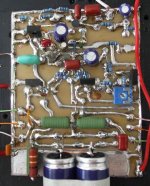
I forgot to include the supply electrolitic condenser we use near the output coletor
It is included into this revision 1
Also a increase to 8600uf or more into the output coupling electrolitic condenser because will work better while using low impedance speakers.
The 72 Volts schematic is almost the same.... transistors will need replacement (some of them for safety reasons) and condensers will need more insulating voltage... power will be more than 50 watts into 8 ohms and distortion will be almost the same (0.008%)... this was checked into simulator but not assembled.
Built, for a while, only the 36V version.
regards,
Carlos
Attachments
- Status
- This old topic is closed. If you want to reopen this topic, contact a moderator using the "Report Post" button.
- Home
- Amplifiers
- Solid State
- Trust, the most delicious Dx Amplifier