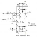
The attached picture is the Holton
Av800 input stage. I'm trying
to avoid using 33uf electrolytic
capacitors on the input and instead
I would like to use 1uf - 5uf
polypropylene capacitors
(or polyester film).
Guessing ----- ------
To achieve the same high pass filter,
can I increase R2 and R7 from
4.7k to 47k and replace the
33uf capacitors to 3.3uf capacitors for
C1 and C4 ?
I'm not sure how to modify the
differential input stage too allow
for a smaller C1 and C4.
Any tips?
Av800 input stage. I'm trying
to avoid using 33uf electrolytic
capacitors on the input and instead
I would like to use 1uf - 5uf
polypropylene capacitors
(or polyester film).
Guessing -----
------To achieve the same high pass filter,
can I increase R2 and R7 from
4.7k to 47k and replace the
33uf capacitors to 3.3uf capacitors for
C1 and C4 ?
I'm not sure how to modify the
differential input stage too allow
for a smaller C1 and C4.
Any tips?
Attachments
Long tailed pair
Your reasoning is correct, but the problem is the input imp of the stage, which is the impedance looking into the base // to R3 which is about 4.7k for the +input. Increasing R2 will attenuate the input signal here 10x, which you don't want.
There is something else that catches the eye here: the -input impedance is much higher, because the bottom end of R6 is bootstrapped by the feedback. That means that the attenuation of R2 to R3 is quite different from that of R7 to R6. As a result, the input sensitivities and input impedances of thee two inputs are quite different. I think C4 can be made much less without any problems: it feeds a much higher impedance.
If I use an unbalanced audio signal and remove
the 33uf input capacitors, would it be ok to short
the -input to the printed circuit board ground plane
and only use +input ?
I'll be laying out a board soon, do you have any
ideas for input stage modifications that I could
incorporate into the design ?
the 33uf input capacitors, would it be ok to short
the -input to the printed circuit board ground plane
and only use +input ?
I'll be laying out a board soon, do you have any
ideas for input stage modifications that I could
incorporate into the design ?
thylantyr said:If I use an unbalanced audio signal and remove
the 33uf input capacitors, would it be ok to short
the -input to the printed circuit board ground plane
and only use +input ?
That is certainly the way to do it with any unbalanced input feeding a differential input. You can also improve things by using a good cap on that feedback to ground. A Black Gate for low voltage won't be expensive and may be a benefit.
Also beware how you route your grounds and do use a star.
Carlos
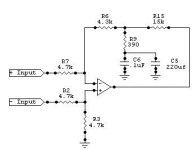
To help me understand how this works, I drew
a block diagram of the input stage using
an op-amp to represent the amplifier and I
removed the input capacitors.
Is this drawing somewhat correct ?
What is the purpose of the 220uf and 0.1uf capacitor?
This type of configuration confuses me
a block diagram of the input stage using
an op-amp to represent the amplifier and I
removed the input capacitors.
Is this drawing somewhat correct ?
What is the purpose of the 220uf and 0.1uf capacitor?
This type of configuration confuses me
Attachments
Homework is for the birds 
But, after searching all day, I found a
reference to that last schematic I
posted......
figure 10 on this website has
the circuit, but without the caps.
http://www.dself.demon.co.uk/balanced.htm
The website claims that this configuration is to allow gain
without affecting CMRR.....
The differential input impedance
is lower on the "cold" leg and
higher on the "hot" leg.., but
common mode input impedance
remains the same for both inputs.....
\\\\\\\\ /////////////
So
What do the caps do ? The
220uf in parallel with 0.1 uf
in the previous picture posted ?
My head hurts
But, after searching all day, I found a
reference to that last schematic I
posted......
figure 10 on this website has
the circuit, but without the caps.
http://www.dself.demon.co.uk/balanced.htm
The website claims that this configuration is to allow gain
without affecting CMRR.....
The differential input impedance
is lower on the "cold" leg and
higher on the "hot" leg.., but
common mode input impedance
remains the same for both inputs.....
\\\\\\\\
/////////////So
What do the caps do ? The
220uf in parallel with 0.1 uf
in the previous picture posted ?
My head hurts
- Status
- This old topic is closed. If you want to reopen this topic, contact a moderator using the "Report Post" button.
- Home
- Amplifiers
- Solid State
- Differential Input Stage - Question