Power supply
ACD,
The suggested power supply source was a 48-0-48/5A that would give around +/-67 volts. However, I have a transformer from a former project that has a secondary voltage of 44-0-44/5A that would give a rectified voltage of +/-62 volts. The thing that strikes me most about the circuit is it looks so simple to build.
Can you show me how to put a pot at the input of the opamp for dc adjustment?
Any other comment about this amp would be helpful.
Thanks,
Jojo
Often it is the most simple designs that works best...
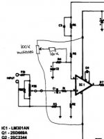
I have build several amps much similar to the one that you are interested in. The design looks very similar to famous older amps like Phase Linear and GAS etc.
Connect the 100K pot between the positive and negative supply to the opamp, and connect the center pin of the pot via 160K resistor to the connection between R4 and R5.
My current amp uses +/- 63VDC, and produces app. 160W/channel into 8 ohm.
Mods
ACD,
Thanks for the mod on the schematic. So this pot will now be used to adjust DC in the output of the amp right?
The suggested output were 2sc2922/2sa1216 transistors, can I substitute it with 2sc3281/2sa1302 but double the number of output xsistors? That would be 8 transistors per channel.
Jojo
ACD,
Thanks for the mod on the schematic. So this pot will now be used to adjust DC in the output of the amp right?
The suggested output were 2sc2922/2sa1216 transistors, can I substitute it with 2sc3281/2sa1302 but double the number of output xsistors? That would be 8 transistors per channel.
Jojo
Yes! This will adjust the DC-offset on the output.
Let the amplifier warm up for 15 minuttes and then adjust it
(offset better than +/- 0,2 mV is possible).
If you use 4 x MJ15003 and 4 x MJ15004 output power transistors per channel, then you don't have to worry about a
protection circuit (I'm talking by experience ).
).
Let the amplifier warm up for 15 minuttes and then adjust it
(offset better than +/- 0,2 mV is possible).
If you use 4 x MJ15003 and 4 x MJ15004 output power transistors per channel, then you don't have to worry about a
protection circuit (I'm talking by experience
).Motorola
ACD,
The MJ15003/4 pairs are still available at a local shop here in my country. They are still stomped "Motorola" and the shop said that these are old stocks and not counterfeit.
Maybe I'll make a prototype pcb and test different output transistors.")
Do you have a schematic of the amp your using now?
Jojo
ACD,
The MJ15003/4 pairs are still available at a local shop here in my country. They are still stomped "Motorola" and the shop said that these are old stocks and not counterfeit.
Maybe I'll make a prototype pcb and test different output transistors.
Do you have a schematic of the amp your using now?
Jojo
this is almost identical to the op-amp based amp I am going to built, except that in my case, I will be using some mosfet in the ops.
It is essentially a CF ops without a va stage. Pretty simple, as you had pointed out.
The only thing that differs from traditional cf ops is the grounding of the emitters of q2 and q3. Does anyone know why?
It is essentially a CF ops without a va stage. Pretty simple, as you had pointed out.
The only thing that differs from traditional cf ops is the grounding of the emitters of q2 and q3. Does anyone know why?
Another amp
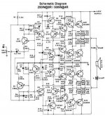
Just want to share a schematic of an amp I used to build. It uses cheap and locally available parts.
The book where it came from said that it can deliver 250W/8ohms and 500W/4ohms. I don't know if that is true because I have no way of measuring the power outputI have successfully built 2 stereo units and we use it for pa purposes. This amp may not be the clearest amp I've heard but it sure is loud! It requires a 35-0-35/25A transformer that is so huge and heavy (22Kg) that the locally available chassis needs reinforcements.
----------------------------------------------------------------------------------
Is there a simple/crude way for me to measure an amps power output? I saw a dummy load at a shop once, I can also borrow a signal injector and a digital voltmeter or whatever they call it. Can I measure an amps output power with these? How?
Jojo
Attachments
Jojo
I only see one 35 Volt supply on the schematic you posted......
I do not have a schematic of amp I'm must happy with at the moment, because it is still "a projeck", but it is very similar to the one that you are interested in.. ..
However I'm using whats called 3-deep-darlington in the output
(a predriver transistor, a driver transistor and 4 output transistors per channel)
MJ15003/MJ15004 are still available in Scandinavia without problems, and will be for the next year or more....
I've have not heard about that they will be obsolete???
But you can use MJ15022/MJ15023 instead.
There are two ways to meassure the output:
The wrong way: using only a 8/4/2 Ohm resistor (as in the specs you see from most manufactures).
For making a correct measurement of the power output you need a 8/4/2 Ohm resistor in series with a coil (app. 3uH) and a capacitor (app. 10uF) in parallel and then meassure the output with an oscilloscope. The true output is the one you can meassure just before the amp clipps
Need advise etc
Jan,
I saw your advise on the DC offset control. But please note that the DC loop gain is about 3 in the amp, so the offset will be limited to less than the intrinsic LM301 offset, which probably is below 10mV anyway. Surely no need to add offset control (which will drift anyway).
On another note, do you suggest to parallell the 10uF to the load resistor for power measurements?? This spells disaster is you measure longer then a few seconds at full power or at elevated frequencies, IMO.
Other Jan (Didden)
Janneman Thanks for joining us.
About DC-offset: I have very good experience with this, and in my amp the DC-offset is below 1 mV on the output!!!
10 mV on the opamp x Voltage gain of the rest of the amp gives a lot of DC on the output......
Regarding the meassurement of output power I can see that it could be missunderstod... Thanks for pointing this out!!
The coil and the capacitor should be connected in parallel and THEN in series with the resistor... NEVER EVER CONNECT A CAPACITOR DIRECTLY OVER THE OUTPUT TERMINALS!!!!!!!
The above mentioned method is very similar to a loudspeaker.
Thanks for joining us.About DC-offset: I have very good experience with this, and in my amp the DC-offset is below 1 mV on the output!!!
10 mV on the opamp x Voltage gain of the rest of the amp gives a lot of DC on the output......
Regarding the meassurement of output power I can see that it could be missunderstod... Thanks for pointing this out!!
The coil and the capacitor should be connected in parallel and THEN in series with the resistor... NEVER EVER CONNECT A CAPACITOR DIRECTLY OVER THE OUTPUT TERMINALS!!!!!!!
The above mentioned method is very similar to a loudspeaker.
Advise etc
Jan,
Yes, now I understand the 10uF.
But I differ on the offset. The LM301A (most loose spec'd version) has a typical 2mV, max 7.5mV offset. And the DC loop gain in this amp is 1x (not 3x as I said before, there is 100% DC feedback to inv input, sorry about that goof). So my 10mV is very, very worst case. I say, putting in the offset control is unneccessary and can make matters worse by drift, potmeter failure etc.
I am sure you are aware that the LM301A is a very tired opamp. Not wanting to go to a faster one, because that can upset the rest of the amp, something like a TL084 or an LF411 is perfectly feasible (you probably can't get the 301 anymore); the latter will bring the uncompensated offset close to 1mV anyway.
Jan Didden
Suppy voltage
ACD,
The supply voltage is single +50v only not 35volts. You see, that is why I want to learn how to measure an amp's output power. I just can't believe that amp can do 250W on an 8 ohm load. However, I don't have any access to an oscilloscope, is there any other way to do this?
Janneman,
Thank you for joining us. The TLO84 is available here in my country but will it just be as easy as a swap or must I change anything from the circuit.
Thanks
Jojo
Janneman,
Sorry regarding the DC-offset. You are right!! I missed the C2 capacitor….
In this case it’s a matter of believes. I like the possibility to adjust the DC-offset, however it is not necessary in this circuit, as you correctly have pointed out.
I think this mistake comes from that I only like to work with DC-coupled amps.
Regarding the choice of opamp there are many types on the marked. If you were building a “common amp” with standard components I would recommend the LF356 (I know that this is an old type, but it has proven to be very rough and it have a fair “sound”). The LF356 is also very cheap. Later you can always change to a more expensive (and maybe better ???) one. But there are no logic in using a high cost opamp and then use standard components in the rest of the circuit. The sound is no better than all the components together. I prefer to use well-known components upper frequency limit of no more than 4 MHz, as this can save you a lot problems with self-oscillation (which f.ex. can be caused by the PCB layout and wiring)
Jojo,
I have looked closer to this 250W circuit and it’s what called a Class H circuit (or bridged H-amp).
This is a technique developed to run an amp from a single supply. If the supply is +50V, each side of the output is designed to “rest” in the middle at+25V (with reference to ground) and with 0V input. Along with the input signal, one amp goes positive on the output and the other negative and then creating a maximum of +48V on one side of the speaker and 2V on the other side (= total of 46V). The rest is just math: 46V : 8 Ohm speaker = 5.75A. 46V x 5.75A = 264W. This is only true if the power supply can deliver the current!!! You can also use these this example to calculate the output power of the amp you wanted to build. However this is the “Asian” (no offends) way to rate the output power…. The correct way is to measure it in real!!!
power ratings
ACD,
I agree with you on the issue of "Asian" power ratings. That is why I don't just trust any amp I find in my country. Shops here "tend" to overrate a power amps output power.
As I've said before, I have built a couple of those 250w bridged amp and they are really loud!
Now, my next project will be the first schematic (150W) that I 've attached. I just hope to find the original parts first. If you do have other suggestions such as possible substitutes to the parts please let me know.
Jojo
ACD said:[snip]Regarding the choice of opamp there are many types on the marked. If you were building a “common amp” with standard components I would recommend the LF356 (I know that this is an old type, but it has proven to be very rough and it have a fair “sound”). The LF356 is also very cheap. Later you can always change to a more expensive (and maybe better ???) one. But there are no logic in using a high cost opamp and then use standard components in the rest of the circuit. The sound is no better than all the components together. I prefer to use well-known components upper frequency limit of no more than 4 MHz, as this can save you a lot problems with self-oscillation (which f.ex. can be caused by the PCB layout and wiring)[snip]
Agreed. Indiscriminately upgrading to the latest, fastest opamp brings a high risk of stability problems as you say. Yes, the 356 would also be OK here I guess, have no experience with it myself.
Jan Didden
Whooaa!
My amp is up and running! Well, I just used a single pair of Mj15024/MJ15025 for the output for testing and it worked ok. Though I had to change a resistor value in the biasing circuit due to a lower voltage rail that I used.
Next step would be to add more output devices or maybe trying out other transistors such as the 2SC2922.
To those who replied to this post, many thanks to you!
- Status
- This old topic is closed. If you want to reopen this topic, contact a moderator using the "Report Post" button.
- Home
- Amplifiers
- Solid State
- Need advise on this amp...