AKSA said:Gaetan,
Certainly sounds plausible, but in the absence of measurement, I can't verify.
Insofar as this is detective work the thrill of the chase is good fun, isn't it?
Ciao,
Hugh
Hello Hugh
Unfortunately, not very much peoples are interested to do deep researchs and tests in that subject, so I am limited to do speculations base on my knowledges of psycoacoustic and electronics.
But as usual I am currious and I always like to do some Sherlock detective work.
How did you find out about the fact that very low levels of H5, H7, H9 can subliminally cause problems ?
Bye
Gaetan
Gaetan,
Simple deduction.
If very low THD still causes irritation, and we know from psychoacoustics that high order is nasty, then it's a logical conclusion.
Tubes in open loop do not do this (listener fatigue); as soon as negative feedback is applied, the problem starts to creep in.
There are holes in these arguments, but I have not figured out what they might be.....
Hugh
Hello
If some guys want to discuss more about all of this subject, maby the moderator can transfer all the concerned posts in a separated new thread.
For those who like to know more about psycoacoustic and ears sound localisation, here is two link;
http://www.aip.org/pt/nov99/locsound.html
http://www.answers.com/topic/sound-localization
Bye
Gaetan
Member
Joined 2009
Paid Member
Everyone,
Again, a thank you for your help and patience to lift me up the ladder, so that I could make an amplifier and pointing me in the direction for making it a bit better. It would not have happened without this Forum.
I think interest in TGM1 must naturally subside and I don't plan to do any further changes to TGM1, so I have decided not to continue with this thread on a regular basis. I started with AKSA as the inspiration for this amplifier and with some help via private communications from 'AKSA" I have been able to achieve some wonderful sounds. My opinion is that there is much to be gained by having the option of an amplifier that was not designed simply for the lowest possible distortion. There is room for both the 'purist' and 'artisticic' approach to defining the goal of good amplifier design.
My goal was not to develop an amplifier for others, so I won't be promoting it as a DIY project, there are better documented amplifier projects on this Forum with similar topologies (+ various web sites), e.g. the Carlos DX amplifier series [http://www.diyaudio.com/forums/showthread.php?s=&threadid=96237] and the Back To The Future amplifier championed by OS [http://www.diyaudio.com/forums/showthread.php?s=&threadid=145306].
TGM2 will have a new thread. [http://www.diyaudio.com/forums/showthread.php?s=&threadid=145652]
====================
Hey Bigun...
I didn't catch where anyone answered your question about the "emitter degeneration" resistors in the LTP... They are a form of local negative feedback and they increase linearity since the error voltage is applied across only the BE junctions (which are exponential in their current-vs-voltage characteristic) without them. (I am a proponent if it wasn't obvious). It doesn't take much error to send one transistor into saturation and the other into cutoff, for which the rather large miller cap in the VA stage is a band-aid to keep the amp from oscillating when the inputs are subject to transient error. The equilibrium voltage drop across those resistors widens the error (dynamic) range substantially (because that voltage will withstand doubling without exceeding the linear range), and increases the frequency onset of slewing (when the entire amp is going as fast as it possibly can to restore order, rather than patiently following the waveform).
In my own designs, similarly to as outlined by W.M.Leach (GA Tech EE professor with very good and stable audio amplifier designs) in his designs, I use hundreds of ohms for LTP emitter degeneration to reduce gain and feedback, and thus distortion, and increase dynamic range by allowing the transistors to both still be in their active regimes even with substantial error. The more you can keep active devices from turning off and/or entering saturation (which can be thought of as "sticky"; it causes lagging distortion because both conditions are sort of momentary commitments for a transistor) in real-world transient conditions, the better.
A design example for me is to have a 2.5 mA bias current in the LTP, with 300 ohm resistors on the emitters. with the 50/50 split at zero error, the drops sit at 0.375 volts, and the response is theoretically linear up to +/-0.75 volts of error. Whether you actually forward the benefit of that linearity to your VA stage is another matter, but you definitely will not have it at your disposal with without any emitter degeneration.
Consider that your (any) amplifier takes a finite time to source or sink current and get the relatively massive speakers moving and return the confirming measurement to the input, so if your audio signal source of choice supplies a step change beyond this voltage reach that is quicker than that finite time, the LTP has its proverbial "needle pinned" until feedback from the output confirms that the universe has returned to sufficient balance, several tens of microseconds later. This is the "transient intermodulation distortion" that some erroneously believe to be mythical.
Without those resistors (and indeed with extremely small values), the error voltage required to produce this ugly condition is quite infinitesimal. The design without them must rely on interstage feedback in the form of bandwidth-consuming capacitors to reduce this problem, causing the amp to simply not bother responding to fast signals rather than chase them hither-and-yon across the voltage rails.
The 'penalty' of degeneration is to reduce open-loop gain. I consider this a minimal trade-off since the gain gets more linear and feedback correction (along with harmonic distortion) is greatly diminished as a consequence.
Sorry about the long-windedness here, but I feel somewhat passionate about this and I see no reason perfectly good people should be making bandwidth compromises for the sake of infinite gain. The greater the open-loop gain, the greater the finesse required in global feedback. The "automotive analogy" would be like having cruise control that could only either give your intakes full throttle or kill the engine entirely until your speed is properly controlled, rather than just applying little bits of effective correction on a dynamic basis.
Note that current mode feedback (like your headphone amplifier design) circumvents this problem in its own way that I am not prepared to explain, and is preferred by some designers.
Member
Joined 2009
Paid Member
Howdy,
Since 'finishing' (it's not really finished) the TGM project I have become a lot more enthusiastic about the application of local feedback via emitter degeneration and my current projects will use this to various degrees.
I haven't given much thought to the question of a limit to the dynamic range of the differential pair at the input. As you say, when there is little phase shift of the feedback relative to the input the input differential will not attempt to generate a large error signal and all is well. I can see that a large phase shift due to a nasty load for example, will compromise the accuracy of the error amplifier with unfortunate consequences. If I'm not mistaken about the work of Graham Maynard, he invented the GEM amplifier to address the issue of the active load messing with the amplifier.
Member
Joined 2009
Paid Member
Well, my chasis and power supply were needed for another project [http://www.diyaudio.com/forums/solid-state/196973-tgm5-all-bjt-simple-symmetric-amplifier.html ] so now my poor TGM1 amplifier is sitting idle. Since it was my first ever amplifier (kind of my first ever electronic circuit for that matter) that I made at home I feel it's a shame not to find a new box.
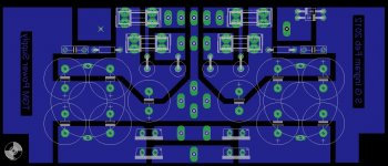
I have found a new box. But now I need to build a new power supply. This time around I'm going to use all Nichicon Gold capacitors, matching those that I used on the amplifier it'self. A new pcb is in the design stage...
And maybe a couple of improvements will be made to my TGM1 modules - nothing major (no topology changes).
Attachments
Member
Joined 2009
Paid Member
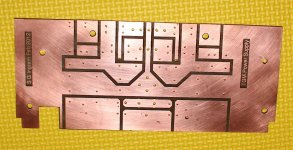
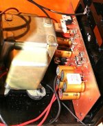
Progress made  - pcb patterned, etched and drilled. The unusual shape is to match up with the new box, itself recycled from an industrial application it has already some mounting holes etc. A recycled trafo from a Yamaha Tuner installed already.
- pcb patterned, etched and drilled. The unusual shape is to match up with the new box, itself recycled from an industrial application it has already some mounting holes etc. A recycled trafo from a Yamaha Tuner installed already.Attachments
Member
Joined 2009
Paid Member


Member
Joined 2009
Paid Member
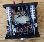
Thanks LC. Well some more progress today. Finished the psu, installed front panel LED indicator. And completed some upgrades to the amplifier:
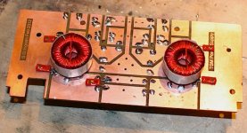
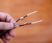
1) added output inductors, some nice ones recovered from a Samsung amp I think with two concentric coils, one inside the other (photo attached)
2) upgraded VAS by removing BD139 and replaced with 2SC3423
3) reduced phase lead comp from 22pF to 5pF silva mica - sims convinced me the old value was 'too heavy', left Cdom at 68pF
some more upgrades may be forthcoming but I need some darn bolts and washers before I can properly re-mount the amplifiers to their heatsinks.
Attachments
Member
Joined 2009
Paid Member
I've completed some further refinements.
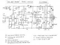
I added emitter degeneration to the LTP, just 4R7 so that I can measure their voltage drop and check to see how well the current flow is balanced between the two LTP devices. I then adjusted the resistor in the collector of the LTP that drives the VAS, until the balance was good. The balance achieved was much better than the original build, with a mismatch of 1.8% on one channel, 3.6% on the other.
I adjusted the series feedback resistor to better match the value of the input resistor - thus ensuring low dc offset on the output. The dc offset is in the range 5mV to 20mV. I used the same values on both channels to keep gains the same. The bias and dc offset appears stable with temperature.
As this is going to be used mainly for near field listening I reduced the overall gain by increasing the value of the feedback shunt resistor from 2k7 to 5k1. This does increase the feedback factor slightly. Simulated OLG is around 48dB and CLG around 20dB.
The speakers used are my own design MARTELLO full range ported boxes.
To my ears these changes have brought about some significant improvements in the sound of the amplifier. It's cleaner without being 'too clean' - simply very nice to listen to. I imagine this is now much closer to the sound that the original AKSA produced. ALSA was the inspiration for this TGM1 design. It's not as precise as my TGM2 or TGM5 but very easy to listen to, relatively easy to build, easy to set up. I'd recommend this design for anyone who normally suffers from listening fatigue to SS amplifiers - you don't get any with this one.
It's also really very quiet, no hum. The trafo is the quietest EI trafo I've ever come across too. Some noises on turn-off.
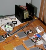
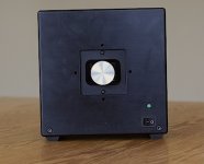
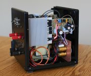
The photos show the rest. Simple black cube, single volume knob on the front, power switch and LED power indicator. The old TGM1 modules are installed either side of the trafo, power supply mounted against the inside of the front panel. The rest of the space used for wiring. There is a simple switch on the back panel as an input selector. The box is closed with a perforated black metal cover.
Now that my kids have discovered this upgrade to the sound of our iMac it's unlikely I'm going to get my hands on it again for some time
I added emitter degeneration to the LTP, just 4R7 so that I can measure their voltage drop and check to see how well the current flow is balanced between the two LTP devices. I then adjusted the resistor in the collector of the LTP that drives the VAS, until the balance was good. The balance achieved was much better than the original build, with a mismatch of 1.8% on one channel, 3.6% on the other.
I adjusted the series feedback resistor to better match the value of the input resistor - thus ensuring low dc offset on the output. The dc offset is in the range 5mV to 20mV. I used the same values on both channels to keep gains the same. The bias and dc offset appears stable with temperature.
As this is going to be used mainly for near field listening I reduced the overall gain by increasing the value of the feedback shunt resistor from 2k7 to 5k1. This does increase the feedback factor slightly. Simulated OLG is around 48dB and CLG around 20dB.
The speakers used are my own design MARTELLO full range ported boxes.
To my ears these changes have brought about some significant improvements in the sound of the amplifier. It's cleaner without being 'too clean' - simply very nice to listen to. I imagine this is now much closer to the sound that the original AKSA produced. ALSA was the inspiration for this TGM1 design. It's not as precise as my TGM2 or TGM5 but very easy to listen to, relatively easy to build, easy to set up. I'd recommend this design for anyone who normally suffers from listening fatigue to SS amplifiers - you don't get any with this one.
It's also really very quiet, no hum. The trafo is the quietest EI trafo I've ever come across too. Some noises on turn-off.
The photos show the rest. Simple black cube, single volume knob on the front, power switch and LED power indicator. The old TGM1 modules are installed either side of the trafo, power supply mounted against the inside of the front panel. The rest of the space used for wiring. There is a simple switch on the back panel as an input selector. The box is closed with a perforated black metal cover.
Now that my kids have discovered this upgrade to the sound of our iMac it's unlikely I'm going to get my hands on it again for some time
Attachments
Last edited:
Member
Joined 2009
Paid Member
Listening impressions from the last month, listening through these:http://www.diyaudio.com/forums/full-range/175056-martello-enclosure-fr88ex.html
Fantastic, I have a renewed respect for this relatively simple topology and numerous refinements guided by Hugh Dean.
No fatigue. Speakers sound a lot larger than they are. Not the last word in transparency, but so nice to listen to.
Fantastic, I have a renewed respect for this relatively simple topology and numerous refinements guided by Hugh Dean.
No fatigue. Speakers sound a lot larger than they are. Not the last word in transparency, but so nice to listen to.
- Status
- This old topic is closed. If you want to reopen this topic, contact a moderator using the "Report Post" button.
- Home
- Amplifiers
- Solid State
- TGM Amplifier ?