Gareth,
maybe I should not say this, however, you get a lot of dirt from E.
maybe I should not say this, however, you get a lot of dirt from E.
Those rumours are explicitly false.some rumours about sonic tradeoffs
It definitely is.Is the RC worth the trouble ?
Much better.Is LC even better ?
I don`t.Do you see a problem if I make the -Ve and _Ve rails on separate pcb's joined by their earths using a solid metal block and then using this as the star gnd ?
Member
Joined 2009
Paid Member
It's interesting to compare the options of C, CRC and CLC.
An inductor with equivalent resistance to an R of 0.22 at 120Hz is around 300uH (if I understand how these things work properly) which gives me the same benefit in terms of ripple rejection but without the voltage drop and of course at higher frequencies the benefits increase rapidly in terms of hf noise. It's about $12/rail:
http://search.digikey.com/scripts/DkSearch/dksus.dll?Detail&name=M8380-ND
- the potential for ringing issues with the CLC worries me a little.
Bigun said:It's about $12/rail:
You could wind your own
An externally hosted image should be here but it was not working when we last tested it.
Digikey has small ferrite "toroids", some magnet wire and the old DIY spirit.
Member
Joined 2009
Paid Member
Member
Joined 2009
Paid Member
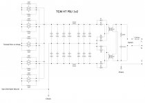
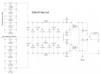
So I've redrawn the psu design with a CLC design, based on the Digikey choke I linked above.
It's not a monster choke because I'm using it to reduce hf noise (e.g. from rectifier diodes) rather than for ripple rejection.
if I've understood it correctly, I get -36dB isolation at 1kHz and -75dB at 10kHz. The CRC set-up would give me only -17dB and -36dB respectively.
Can you see any traps I've fallen into with this set up ???????????????
The diodes are good to 8A continuous, 16A repeated pulse at 50% duty cycle. I figure this is good enough when 'full power' from the secondaries is less than 7A (18V secondaries).
Total capacitance per rail is 10.8mF (50V). It's not great for ripple if operated at the max. current rating of the secondaries but this isn't supposed to be how it's used.
Attachments
Member
Joined 2009
Paid Member
Hi Lumba,
I'm afraid I'm too lazy to find a bigger L. But MJL has me curious so I'll read about the DIY options. Still, the key thing is that it's still way better than the CRC for high frequency hash reduction.
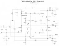
Updated Schematic / BOM:
I had a couple of emails asking me for BOM. So time to reset. The little pcb I made and populated with parts is the basic version, TGM1v8. The schematic is repeated here (attached).
some comments: this is planned as a nominal 25W module in a multi-channel amp for use with sensitive speakers. The source is a Blu-Ray player which has a 10kOhm 2Vpk-pk output. This means that I don't need a high level of gain from this amplifier, in fact I have to add an attentuator /volume control yet.
So the value of R9, which sets the overall amplifier gain may yet be tweaked to suit my set-up. I'm starting off with a relatively conservative gain.
I have also some space restrictions and I want to keep thins neat and tidy whilst I experiment. So I have NOT included a few items onto the pcb. These are:
R21, R22, F1, F2 - the power rail fuses and resistors. I plan to put these on the psu board instead so I can see all my fuses in one place. For people powering up the amp for the first time, it's recommended that you do so without fuses but with R21 and R22 in place to drop the voltage/current and so protect the amp in case there are some problems.
C10, C11, C12, C13 are the power supply filter/decoupling and I've left these off because I expect to have short connections from the power supply to the amp. This goes against all recommendations so anyone trying this does so at their own risk.
R2, D2, D3 are also excluded from the board. I plan to include all the ground lift resistors on the volume/attenuator pcb which will be mounted near the rear panel where the signal inputs are located.
Lastly, L1 is not included on my pcb because most likely I won't need it. If I do get instability then I'll have to put them in. I will install them not on the pcb but close to the speaker binding posts on the chasis rear panel.
Some other comments: The supply voltage for 25W should be enough to achieve around +/-24V rails under load. Given a +ve supply rail voltage, the bias current through the LTP (T1 and T2) is set (approximately!) by i = +Ve supply / R3. As said earlier I'm planning to use a low bias current, somewhere between 0.5mA and 1.0mA. I've populated my pcb with a 39k resistor. You may want to experiment with this value.
I'm afraid I'm too lazy to find a bigger L. But MJL has me curious so I'll read about the DIY options. Still, the key thing is that it's still way better than the CRC for high frequency hash reduction.
Updated Schematic / BOM:
I had a couple of emails asking me for BOM. So time to reset. The little pcb I made and populated with parts is the basic version, TGM1v8. The schematic is repeated here (attached).
some comments: this is planned as a nominal 25W module in a multi-channel amp for use with sensitive speakers. The source is a Blu-Ray player which has a 10kOhm 2Vpk-pk output. This means that I don't need a high level of gain from this amplifier, in fact I have to add an attentuator /volume control yet.
So the value of R9, which sets the overall amplifier gain may yet be tweaked to suit my set-up. I'm starting off with a relatively conservative gain.
I have also some space restrictions and I want to keep thins neat and tidy whilst I experiment. So I have NOT included a few items onto the pcb. These are:
R21, R22, F1, F2 - the power rail fuses and resistors. I plan to put these on the psu board instead so I can see all my fuses in one place. For people powering up the amp for the first time, it's recommended that you do so without fuses but with R21 and R22 in place to drop the voltage/current and so protect the amp in case there are some problems.
C10, C11, C12, C13 are the power supply filter/decoupling and I've left these off because I expect to have short connections from the power supply to the amp. This goes against all recommendations so anyone trying this does so at their own risk.
R2, D2, D3 are also excluded from the board. I plan to include all the ground lift resistors on the volume/attenuator pcb which will be mounted near the rear panel where the signal inputs are located.
Lastly, L1 is not included on my pcb because most likely I won't need it. If I do get instability then I'll have to put them in. I will install them not on the pcb but close to the speaker binding posts on the chasis rear panel.
Some other comments: The supply voltage for 25W should be enough to achieve around +/-24V rails under load. Given a +ve supply rail voltage, the bias current through the LTP (T1 and T2) is set (approximately!) by i = +Ve supply / R3. As said earlier I'm planning to use a low bias current, somewhere between 0.5mA and 1.0mA. I've populated my pcb with a 39k resistor. You may want to experiment with this value.
Attachments
Member
Joined 2009
Paid Member
Here's the BOM (attached) for TGM1.8F.
The blue colour highlights items not installed on the pcb.
I haven't yet 'invested' in audio quality resistors. If I ever do, it will be for those in the signal/fdbk path like R9 R13, R14 etc.
I haven't invested in 'boutique' capacitors either. But I did choose good quality capacitors, including 'audio grade' for C4 an perhaps in a flash of enthusiasm I also used this type for C3 which filters the front end supply.
There are some options I have been thinking of, those are for future experiments.
Attachments
Member
Joined 2009
Paid Member
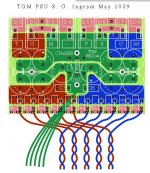
And lastly the pcb - I put this up in post 144.
Some comments. Unlike most others I've seen, I placed the two output devices next to each other. This might create a hot spot on the heatskink if not done properly. I did this so that I could isolate the high-current paths to one corner of the pcb. Not only does this minimize resistance but it means a small inductance loop - in some designs the whole of the circuit sits inside the loop formed by +ve and -ve rails and I'm not sure if this is good. I put the charge suckout cap right by the devices.
I also put all the connections at one point, so I could install a header on the pcb edge. Although not necessary, it appealed to my sense of cleanliness.
All the voltage-sensitive and low current circuitry is located in the opposite corner from the high current output devices. There are no cases where high current signals go anywhere near these parts of the circuit.
Hopefully the build of these considerations regarding signal routing and component placement are obvious in that they follow conventional wisdom.
There are no links.
Member
Joined 2009
Paid Member
Member
Joined 2009
Paid Member
And now looking to the power supply. Updated to single board, Chokes mounted underneath. I've allowed two 2,700uF on each rail before the choke, another two after the choke + a third spot which can be populated with an extra 2,700 cap or a 1,800 / 1,200 / 560uF as they are all available in the same footprint.
Should be able to get this pcb made and populated this week. Then, if it works as planned, I have something to test the amp with")
Should be able to get this pcb made and populated this week. Then, if it works as planned, I have something to test the amp with
Attachments
Member
Joined 2009
Paid Member
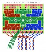
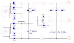
Hi Gareth,
You might want to consider splitting the ground as shown below. The 100 ohm resistor (with opposed diodes) isolate the audio ground from the chassis ground. Helps (I think) to eliminate ground loops and keeps some of the high frequency noise from the diodes and bypass caps out of the audio ground.
You might want to consider splitting the ground as shown below. The 100 ohm resistor (with opposed diodes) isolate the audio ground from the chassis ground. Helps (I think) to eliminate ground loops and keeps some of the high frequency noise from the diodes and bypass caps out of the audio ground.
Attachments
Member
Joined 2009
Paid Member
This forum is good at keeping me honest - I had slipped in a little change to simplify the grounding but you are right, it's not the best approach.
Trouble is, I cut the raw pcb board, so now if I make changes it has to fit on the same board. A challenge I can meet no doubt.
How does this approach match up to the ground lift resistors on the signal inputs ?
** I am concerned about instability in the psu because of these chokes though. The L and total C produces some options for oscillations does it not ? - can anyone put my mind at ease on this point ?? **
Bigun said:This forum is good at keeping me honest - I had slipped in a little change to simplify the grounding but you are right, it's not the best approach.
Trouble is, I cut the raw pcb board, so now if I make changes it has to fit on the same board. A challenge I can meet no doubt.
How does this approach match up to the ground lift resistors on the signal inputs ?
:
I just wire my audio input socket to the chassis which is earthed and dont get any problems.
The only equipment I connect to the amp are a cd player and a guitar effects pedal so its unlikely I will get two earths.
If it was a problem I would use a switched earth on the amp.
How does this approach match up to the ground lift resistors on the signal inputs ?
I used both in my 6 channel amp to good effect.
Oscillation shouldn't be a problem...
Member
Joined 2009
Paid Member
Member
Joined 2009
Paid Member
- Status
- This old topic is closed. If you want to reopen this topic, contact a moderator using the "Report Post" button.
- Home
- Amplifiers
- Solid State
- TGM Amplifier ?