Bigun said:However, I read a posting in a forum that it uses 68k as the default load for the LTP. Looking at the limited data I have for 2N5401 I don't see why the lower current (0.5mA) would be a problem (does it hurt linearity or frequency response ?)
Looks like you are starting to have fun

Here's my take on it:
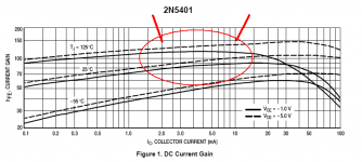
There isn't a default load for the LTP. You need to determine what the current through the stage should be and make it so. To do this, you look at the device current gain plot. Ideally, you want to be smack dab in the middle of it's most linear range, given the operating temp and the dissipation. See the attached chart.
Attachments
Member
Joined 2009
Paid Member
That makes sense - you don't want the gain varying with the signal current. This seems to be one of the limitations that it's necessary to work around. As you say, you have to pick a spot. It would be interesting to put a pot in here and listen to the difference it makes to the sound. But the current impacts the dc operating points of other parts of the amplifier.
It would be nice to simulate this in advance, but.....
There are virtually no spice tools for the Mac. The only one which runs and uses a decent graphical interface (rather than some unix command line mode) is called MI-Sugar. It's no longer supported, you will be hard pressed to find it. And so far I have been unable to get it plot any results or run complex analysis.
Ccan't give up.
Member
Joined 2009
Paid Member
update...
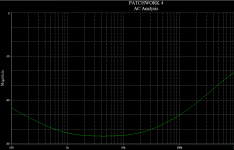
seems that 'ac voltage source' and 'sinusoidal voltage source' are different things. Now I can run an ac analysis (small signal). No plots though (darn). I think what I see is that if I inject a 1V amplitude signal to the input I see that it appears on the base of T1/2. About 1mV of this appears at the base of the PNP. None of it appears on the supply rail.
seems that 'ac voltage source' and 'sinusoidal voltage source' are different things. Now I can run an ac analysis (small signal). No plots though (darn). I think what I see is that if I inject a 1V amplitude signal to the input I see that it appears on the base of T1/2. About 1mV of this appears at the base of the PNP. None of it appears on the supply rail.
Attachments
It's a shame you have just have a mac. With windows I can't run
mac programs. For linux ,"wine" can virtualize a win32 program.
(I CAN run LT4 on my Ubuntu Linux)
Here is something that might help,
http://www.codeweavers.com/products/cxmac/
It let's win32 programs run on a newer mac (intel based)
never tried it but it might work.
MJl was right, the 2n5401's work far better at 2mA.
I never built a amp without a current source , so your
TGM got me curious. I took out one of my CCS's and
cranked the other channel... I could definitly hear
crosstalk(the other channel).. so , you might want to reconsider current
sources unless you are going to use totally separate
PS's for each channel . also , Distortion is 5X without
the CCS because too much "garbage" re-enters at the LTP
emitters , modulating the gain,
which even negative feedback can't fully compensate for.
Some amps use a separate regulated supply for just the VGS, (LTP and VAS) and a 'brute" supply for the output section.
My new one will be adaptable for that. (attached) note the
split on the side where the V- goes...there I could take
your route, as the supply would already be "clean" with
little load (ripple).
The original destroyer X amp is like yours , but carlos added
a zener to the current "side" of the LTP that acts as a primitive regulated source.(I think his original inspiration was the aska55
as well).
OS
Attachments
Member
Joined 2009
Paid Member
Good catch! Power Supply: I only need 25W channels (so I should be thinking about +/-24V supply?) to drive my single driver DIY speakers; a single toroid would work. I don't think AKSA, without it's CCS was designed for such an environment. For HT I don't worry about some cross-talk, operated bridged for stereo and I may have to worry.
But...the update to AKSA 55 is LifeForce 55, which does use a CCS and people have reported that it doesn't sound as sweet as the AKSA 55 ? I am convinced that one of the 'secrets' is having distortion, just has to be the right kind. Actually, I haven't read anybody claiming to have an amplifier based on this topology that sounds as sweet as AKSA at the hi end so it's a tough target !
I will keep CCS as an option.
p.s. I'm checking out that link...
Member
Joined 2009
Paid Member
So here we go with improved current source. I didn't like the zener idea, not because of any personal experience but because I read that they are noisy - especially those that operate above 5.6V where they rely on tunneling instead of breakdown. There is a way to fix this by adding a transistor, but then you have to add another diode for temperature compensation. Needless to say I picked the non-zener approach. I have thrown in a pot so that I can 'play' with the LTP current and use this to fine-tune the o/p offset.
Attachments
ostripper said:
I never built a amp without a current source , so your
TGM got me curious. I took out one of my CCS's and
cranked the other channel... I could definitly hear
crosstalk(the other channel).. so , you might want to reconsider current
sources unless you are going to use totally separate
PS's for each channel . also , Distortion is 5X without
the CCS because too much "garbage" re-enters at the LTP
emitters , modulating the gain,
which even negative feedback can't fully compensate for.
?
Funny, I have an amp design with NO active current sources.
I must have been lucky (or did something right) - PSRR plot below.
Plays out in real life with 6 REAL amps on the same PS, no crosstalk.
And distortion? I think we already know the answer...
Attachments
Member
Joined 2009
Paid Member
I've made some progress in that I've persuaded my Mac to do a dc operating point analysis on what is nearly the full schematic.
1) Trouble is, to get balance (offset at output still too high at 97mA) the LTP it's running at 19mA (too high no doubt) so is the recommended method to address this with a collector resistor on T2 ?
2) I don't have Spice model parameters for several devices - can anyone help me here ?
2SC5200
2SC1943
2SA1837
2SC4793
2SC1819
p.s. I've tried running small signal 'ac' analysis. I need to read up on this a bit more because it looks as if it's telling me I have unity gain - oops I think I have 100% NFB
Thanks for the help so far !
Attachments
By mjl- Funny, I have an amp design with NO active current sources.
But you do have a cascode/current mirror. that is not the same
as having nothing, as on the TGM.
OS
Bigun said:1) Trouble is, to get balance (offset at output still too high at 97mA) the LTP it's running at 19mA (too high no doubt) so is the recommended method to address this with a collector resistor on T2 ?
Change R9 to 47k. It will help to keep the DC balance.
Sajti
Member
Joined 2009
Paid Member
Hi Sajti - I've made that change and completed the schematic with a couple more items. I'e adjusted the bias to get around 50mA though the output devices. The small signal ac analysis puts about 30V at the output for a 1V input.
I think I have better appreciation for the dc operating points but the ac analysis is still too much of a mystery. And I am still missing spice models for everything except the 2N5401's.
I think I have better appreciation for the dc operating points but the ac analysis is still too much of a mystery. And I am still missing spice models for everything except the 2N5401's.
Attachments
Re: RE: schematic in post #1
+
remove C6
fjr said:Looks OK, but I think some mods are needed.
First, add an RC filter to the negative rail too, anyway you'll get low PSRR.
I'm not sure D1 is needed.
Then R1 must be = R9.
C4B would blow. Omit that.
A 100n...1u foil cap in paralel with R15 would be a good idea. R15's value is too low.
Add resistors is serier with C11 and C13 (1r...10r).
Use some lag compensation as OStripper suggested is his schema.
Omit L1 if the amp is stable driving capacitive load without the inductor. Or add a low value resistor in paralel with the inductor.
Use CFP Vbe multiplier or the bias will vary with rail variation.
I cannot agree with OStripper related to emmiter degeneration. I don't think they are needed in this circuit.
Current source and current sink for the LTP are not needed. Keep it simple.
An RC is needed in the input for lowing TIM (series R, paralel C).
Good luck!
+
remove C6
Member
Joined 2009
Paid Member
Time to review all the advice and check that I've covered everything...
1. serves two purposes, one to allow 'safer' operation of the amp when first built without fuses installed, second to keep the supply rails up after a fuse-blow which should help avoid a sudden and large dc at the output along with fried speaker coils.
1. I've added a pot (P1) to allow adjustment. In the simulation I've initially dropped this to 470R which gets me up at 3mA total LTP (and correspondingly I dropped R4 to 470R to restore the balance a bit)
2. 100R added to each emitter.
3. T3 Miller cap seems to be something affecting sonics, maybe I will adjust this via listening tests. Fixed the low emitter-to-emitter driver resistance
4. Fixed my positioning of the 22pF cap ..based on my belief that AKSA has this cap on the collector side of T4 ?
5. the aim is to keep close to AKSA which I've read has an i/p impedance of 47k - perhaps this needs to be updated when I have the source defined. Right now it might end up being a Sony Blu-Ray S-550 with analogue outputs but I don't know how well they've implemented the ADC in this player and then there's the matter of volume control... For sure I need to look at the gain (open and closed loop), I haven't done a good job of understanding this yet.
6. Done.
1. Hugh Dean reported that he found a positive benefit from putting D1 into the positive rail, but didn't hear a benefit from doing so in the negative rail. I'm not sure if it's connected to that reason but I've read of claimed benefits to the bootstrap for D1 (if I'm right, check out a patent by Zenith Electronics Corp from 1994 US Patent 5315263). I have included an RC into the negative rail.
2. done in latest schematic.
3. perhaps it was a case of too little knowledge being a dangerous thing, but I ready a post (I think by Hugh ?) about replacing the C4 on AKSA with two Blackgate caps mounted back to back like that as an optional upgrade. Anyhow, that was removed.
4. I have increased the driver emitter-to-emitter resistance. I've added a 100nF cap. My understanding is that this (from Self) helps reduce the consequences of cross-over distortion from the o/p when in Class AB.
5. Why ?
6. I haven't looked at the high/low-freq lead/lag at all so I need to understand this more.
7. I'll leave this in the schematic as a reminder, but I will test it out without using this. The speakers in mind should be easy to drive. Hugh mentions that a resistor in parallel is advised on AKSA 100 but unnecessary on AKSA 55 (although he includes it since it's easier not create different parts)
8. the diodes were just a temporary thing that allowed me to play with the LTP.
9. I am not sure AKSA 55 has these either but I added them anyway because it turns out to be very handy - they allows a quick assessment of the current flow through each of T1/T2 via a simple voltage drop measurement.
10. I think I'll stay away from the current mirror but I've included a simple 'regulator' at the top based on a green LED. Something cool about green LED's !!! (and it's now included in Lifeforce 55, the successor to AKSA).
11. do you really think TIM will be a problem with this design ?
nigelwright7557 said:1. Not quite sure you need 100R resistors in paralell with fuses
1. serves two purposes, one to allow 'safer' operation of the amp when first built without fuses installed, second to keep the supply rails up after a fuse-blow which should help avoid a sudden and large dc at the output along with fried speaker coils.
ostripper said:
1. not enough current across T1/2 , 10k for R3 solved that.
(1.4ma per device)
2 . no degeneration on T1/2 .. too much gain , also R9/1
too high. ( amp produced a square wave with 1v input).
3. I used 100pF for C5 (safe) and r15 way too low.. 100R
is better.
4.with aksa's 22p ..the amp has a very good loop gain response
(won't oscillate)
5. and 27k for input and feedback give enough closed loop gain.
6. you might want to increase C3 (22u) to 100u, less offset at output.
1. I've added a pot (P1) to allow adjustment. In the simulation I've initially dropped this to 470R which gets me up at 3mA total LTP (and correspondingly I dropped R4 to 470R to restore the balance a bit)
2. 100R added to each emitter.
3. T3 Miller cap seems to be something affecting sonics, maybe I will adjust this via listening tests. Fixed the low emitter-to-emitter driver resistance
4. Fixed my positioning of the 22pF cap ..based on my belief that AKSA has this cap on the collector side of T4 ?
5. the aim is to keep close to AKSA which I've read has an i/p impedance of 47k - perhaps this needs to be updated when I have the source defined. Right now it might end up being a Sony Blu-Ray S-550 with analogue outputs but I don't know how well they've implemented the ADC in this player and then there's the matter of volume control... For sure I need to look at the gain (open and closed loop), I haven't done a good job of understanding this yet.
6. Done.
fjr said:1. First, add an RC filter to the negative rail too, anyway you'll get high PSRR. I'm not sure D1 is needed.
2. Then R1 must be = R9.
3. C4B would blow. Omit that.
4. A 100n...1u foil cap in paralel with R15 would be a good idea. R15's value is too low.
5. Add resistors is serier with C11 and C13 (1r...10r).
6. Use some lag compensation as OStripper suggested is his schema.
7. Omit L1 if the amp is stable driving capacitive load without the inductor. Or add a low value resistor in paralel with the inductor.
8. Use CFP Vbe multiplier or the bias will vary with rail variation.
9. I cannot agree with OStripper related to emmiter degeneration. I don't think they are needed in this circuit.
10. Current source and current sink for the LTP are not needed. Keep it simple.
11. An RC is needed in the input for lowing TIM (series R, paralel C).
1. Hugh Dean reported that he found a positive benefit from putting D1 into the positive rail, but didn't hear a benefit from doing so in the negative rail. I'm not sure if it's connected to that reason but I've read of claimed benefits to the bootstrap for D1 (if I'm right, check out a patent by Zenith Electronics Corp from 1994 US Patent 5315263). I have included an RC into the negative rail.
2. done in latest schematic.
3. perhaps it was a case of too little knowledge being a dangerous thing, but I ready a post (I think by Hugh ?) about replacing the C4 on AKSA with two Blackgate caps mounted back to back like that as an optional upgrade. Anyhow, that was removed.
4. I have increased the driver emitter-to-emitter resistance. I've added a 100nF cap. My understanding is that this (from Self) helps reduce the consequences of cross-over distortion from the o/p when in Class AB.
5. Why ?
6. I haven't looked at the high/low-freq lead/lag at all so I need to understand this more.
7. I'll leave this in the schematic as a reminder, but I will test it out without using this. The speakers in mind should be easy to drive. Hugh mentions that a resistor in parallel is advised on AKSA 100 but unnecessary on AKSA 55 (although he includes it since it's easier not create different parts)
8. the diodes were just a temporary thing that allowed me to play with the LTP.
9. I am not sure AKSA 55 has these either but I added them anyway because it turns out to be very handy - they allows a quick assessment of the current flow through each of T1/T2 via a simple voltage drop measurement.
10. I think I'll stay away from the current mirror but I've included a simple 'regulator' at the top based on a green LED. Something cool about green LED's !!! (and it's now included in Lifeforce 55, the successor to AKSA).
11. do you really think TIM will be a problem with this design ?
Attachments
Member
Joined 2009
Paid Member
I found some spice models for the output and drivers (a post made by OS somewhere) and loaded them in.
I Fixed up a couple of schematic errors.
I think this is as far as I can go for now without better sim capability.
I'd like to understand where the bulk of harmonic distortion comes from. I read that higher order are generally 'bad' and lower order (2nd, 3rd) are subjective. How do I 'play' with the 2nd and 3rd without generating a bunch of higher orders ? Is this mostly determined by the performance of the LTP - I'd like to know what the distortion looks like when the LTP current is low (without current mirrors).
Attachments
by BG - I'd like to understand where the bulk of harmonic distortion comes from
I ran into that same "wall" a while back. As far as how much distortion , that is what NFB is all about. How faithfully the LTP
and VAS can amplify the signal before feedback is applied
will determine the total THD. The type of distortion (H2/3/5/7)
has a lot to with both the balance of the LTP and type of
VAS.
In the attached plots (A , B , and C), A is a fully balanced
LPT (only microamps difference between sides),
B is a standard blameless with current mirror (still not
balanced, but better - .05ma),
and C is close to the TGM (No CM , with bootstrap).
B and C are just about the same amps , except one has the
mirrors and one has the bootstrap (C). B.. the blameless
give much more distortion than A , but the reason is
obvious, if you look at the waveforms at each transistor in the
pair (they are not the same) .Also B's VAS is sinking (or sourcing)
against a fixed CCS) UNBALANCED , but it still works , just
not at .001% or below.
C, the bootstrap... is quite unbalanced at the LTP, but it
has that "out of phase" feedback through the big cap at
it's VAS , also.. it attenuates the higher order harmonics
because it is just another filter. this is why it is more H2
"heavy" and has a better sound.
The attachment shows all 3 , 100W -1K... just about any device will
show the same results.With "A" ,just for fun , I unbalance
the input pair.. total distortion and H3/5 go way up.
On B and C , using a high gain device for VAS (or a emitter follower) reduces the load on the LTP and reduces total THD
AND H3/5/7.
OS
Attachments
Member
Joined 2009
Paid Member
Thanks OS, I appreciate the time spent; this kind of comparison is very handy and something I can't get my software to do yet. I can see there's much still to be learned and I need to read up on Blameless as I've not seen this one yet.
I wonder if it's possible (and has been tried) to play with the balance of the LTP whilst listening to the affects in real-time ?
Perhaps to make this more controllable it's necessary to strengthen the driving ability of the LTP so it's only the imbalance that's changing and not also something else. From your sim it seems that reducing the loading on the LTP would reduce the higher order harmonics but not H2 ?
To do this, I could add a complimentary device to each LTP device. This doesn't create a mirror but then I could tweak the imbalance directly (see attached). I saw a topology like this whilst reading about 'memory effects' from thermal transients by a French guy at http://peufeu.free.fr/audio/memory/memory-4-circuits.html
look at fig 4-2 option B. One of the options uses a jFet too, which I've not seen in a combination like this only on a schematic posted somewhere around here of a British Armstrong amplifier.
Attachments
By BG- I saw a topology like this whilst reading about 'memory effects' from thermal transients by a French guy at
I see you have found the comp. feedback pair input stage by
the "french guy". I built that , and in reality , I could hear no real
"magic" over a typical LTP. In simulation , there was a different
ratio of H2 vs 3 doing the FFT's on the circuit.
The switch to fully balanced operation however.. ,was audible.
The "symasym" was one step in the right direction...
http://www.diyaudio.com/forums/showthread.php?s=&threadid=60918&highlight=
and tom holman's "APT" amp was where I ended up.
These amps load both transistors in the LPT equaly,
one does it with a current mirror in the VAS (symasym),
the holman (attached) ,uses a "level shifter" current mirror off the
LTP. Both load the input pair within uA's of each other.
This initially has the effect of making THD super low and
higher order distortions nearly disappear.
Since P and N channel transistors in the VAS always have
slightly different characteristics , a trimmer is added to
balance the CM.
OS
Attachments
Member
Joined 2009
Paid Member
Hi OS,
Thanks for explaining.
I like that symasym design to my eyes it looks quite elegant.
edit: It also looks really like the Armstrong 732 Power Amp ?
If I go back to my original aim it was to reproduce what people tell me the AKSA 55 has - a certain musicality (and it was a simple design). But this circuit is secret. However, Hugh was kind enough to spill the beans regarding one of the secrets - that being the level of low harmonics 'designed in'. This means I don't want very low THD but I do want to be able to control it. I have read that Hugh has taken AKSA 55 to a new level with the LF55 but in doing so made it better and cleaner so that the lower order harmonics are much reduced - he recommends a tube pre-amp.
I'm not sure which topology gives me the best control, ideally after the thing is built rather than being fixed at the design. I been heading towards the Frugalamp front end (attached) using two pots to control the total current flow through the LTP and the balance but perhaps sysmasym also allows the same control ?
Another thing that has me wondering is the feedback. The low freq. gnf makes sense via the resistor network. But the high freq. is not so clear. Leach mentions taking it from the driver stage for improved stability. Is this the only consideration ?
Attachments
Member
Joined 2009
Paid Member
Another question - pre-amps. If I plan to hook the final creation up to a Blue-Ray player's line-out I will want a 5-channel ganged volume control (sub is independent). I understand that this can be accomplished with a passive divider on the input.
But I wonder if this is the recommended route ?
So I popped over to look at Nelson's pages (first time, wow - they are interesting !) and it got me thinking about a JFET pre-amp. And the hidden agenda here would be to leave it to the pre-amp to add 'colour' or not to the sound and build the TGM-Amp as clean as possible.
Thoughts ??
Still - the LTP does give some room for 'play'
Another thing that has me wondering is the feedback. The low freq. gnf makes sense via the resistor network. But the high freq. is not so clear. Leach mentions taking it from the driver stage for improved stability. Is this the only consideration ?
? #1 .. for your original "TGM" (aksa clone) the open loop gain
plot shows all (attached) with 22pf HF NF from VAS, it is good
(226k unity gain, 90+ phase at UG) very typical for a bootstrap
type topology (cap rolls HF off at >200k). Aska takes HF NF
off at VAS , perhaps not including the OPS in the loop gives
the "magic" sound?? Ratio of DC FB resistor to main NFB
resistor gives total gain of amp , but changes
only affect OLG slightly.
you would have to spec out what the blue ray does for OP.Thoughts ??
A passive divider is ok , but will change the input impedance to the amp slightly.(affecting gain)
A simple Buffer/ X2 non -inverting -opamp
(with tone controls)
http://sound.westhost.com/project02.htm
,will give enough "boost" for low level media.
I just use PC soundcards to drive the frugalamps and at 1.7v
can almost clip the outputs.
OS
Attachments
- Status
- This old topic is closed. If you want to reopen this topic, contact a moderator using the "Report Post" button.
- Home
- Amplifiers
- Solid State
- TGM Amplifier ?