Member
Joined 2009
Paid Member
Member
Joined 2009
Paid Member
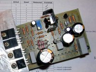
It looks a bit messy, but it's the first prototype. The heatsink is temporary and I haven't sorted out the electrical isolation between the devices tabs and the metal. Also haven't sorted out the VBE multiplier device connections. Flux residue everywhere, need to find some flux cleaner before this thing sees any kind of power supply.
At least if it doesn't work and can't be debugged within my skills, I can pot it in some perspex and use it as a paperweight
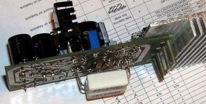
Here we see the output emitter resistors placed on the underside
At least if it doesn't work and can't be debugged within my skills, I can pot it in some perspex and use it as a paperweight
Here we see the output emitter resistors placed on the underside
Attachments
Gareth,
Lookin' good!
Are you using TO220 output devices?
Do you have any rail caps for decoupling the supply?
Like the emitter resistors foil side, nice touch.
Where are you putting the Vbe multiplier?
I use meths spirit, then when it's dry, brush away the residue (which is non-conductive) with a nail brush. Then I lacquer it with a proprietary product.
Cheers,
Hugh
Member
Joined 2009
Paid Member
Lumba - nice to know that works, I have a can of that, will give it a try tomorrow.
Hugh,
Yes, I have the TO-220 output devices. For the power level I'm using they appear adequately rated and were available from DigiKey which was convenient. They aren't Toshiba though (Fairchild), so we may not achieve the same sonics as AKSA with this (even assuming that the other elements I have were similar). I'm not against 'upgrading' to the bigger devices if it makes sense but not sure if this is necessary.
No rail caps on this board. I don't think I had a good reason to leave them off (yikes !). I'll have to add something to the bench supply wires for testing purposes. How close to the board do these caps need to be ? Do they have to go on the board, or could they be stationed separately with the psu if distances between them are short ? Overall, decoupling has not been given much attention and I may end up adding something on the underside if necessary.
The VBE device was supposed to go on top of the output device (which like the underside emitter resistors was a nod to your design approach). But with the TO-220 this isn't so practical and is essentially an oversight on my part. I'll have to find it a home on the heatsink adjacent to one of the output devices. It would be nice if there were some way to cement it directly to an output device but this likely means never being able to separate them so I'd have to replace both devices if one of them fails.
I think your approach is fine, and will work well. As far as I can see your amp should sound very good vis a vis an AKSA.
The advantage of the TO-3P is that you can indeed locate a TO-126 Vbe multiplier right on top, giving very fast reaction to heat output. The disadvantage is the need to attach flying leads to the multiplier, which is fine work. Your approach will be fine, however, though a little slower to react, but that's no bad thing.
Decouplers compensate nicely for inductive swing in the supply leads which can greatly increase distortion because of voltage sag, and in extreme cases lead to oscillation. I use 100uF on each rail with a 150nF film bypass. It's nice to have them within a couple of inches of the output devices.
You might consider using a 100nF quality filmcap across the 220R resistor between the driver emitters. It is Self's preferred arrangement - the Type II EF - and the cap promotes removal of minority charge carriers from the base of the output device as it de-activates with each alternate half cycle.
Cheers,
Hugh
Member
Joined 2009
Paid Member
Hugh,
Currently I have put a 150nF polypropylene charge suckout between the base of the output devices. It's not exactly across the 220R resistor (R15) since it sits on the other side of the base stoppers (R16 and R17).
I need to think about this decoupling, my understanding is not complete yet. The LTP and VAS are decoupled with 100uF on both rails. I thought the output devices are not nearly as sensitive to supply rail noise (based on Spice without inductance in the supply delivery) ? - I must be missing something because everyone includes these caps.
Best to find out now rather than after the final design is heading for pcb fabrication !
p.s. you probably noticed that the ground-lift (R2) is missing also. I'm planning to put this on a separate pcb which will include the volume control.
Gareth,
Ground lift from signal/fb ground to power earth is critical, and should be bypassed with two 1A back to back diodes and a parallel 10R resistor.
Only one 100uF decoupler is required for LTP and VAS together. This is important, too much is bad.
Different simulators can tell two different stories - simulators are not identical, it appears. I've had low distortion figures (sub -80dB) on LTSpice, a good friend has very different figures. I believe the differences lie with the models, and they are not yet 100% for LTSpice, though Andy_C's are evidently very good.
The simulators tell you if it will work, not how it will sound, and correlations between the schematic and the sound are very difficult to divine. It is anyone's guess what the ideal distortion profile should be, although low levels of higher odd orders are mandatory. Unfortunately building is still necessary.
If there is sufficient inductance in the supply rails, then the output devices can still oscillate - their Ft is still around 30MHz, after all. You can minimize this inductance by twisting pos and neg rail wires together.
Cheers,
Hugh
Member
Joined 2009
Paid Member
Hugh,
I will certainly add the R2 + diodes. I left them off to start with as I was considering using a common signal ground where the RCA cables come to the chasis so I'd have only one ground-lit resistor for all 5 channels instead of individual ground lifts on each one. That part of the design hasn't been thought about much yet.
Why does the -ve supply rail cap for the VAS present concerns ??? in my simulations (darn things) I found it essential to prevent xtalk between channels unless I implement 5 separate supplies. With this simply cap/resistor I can use a single supply with negligible xtalk, but if I use only a cap/resistor on the +ve rail then there is virtually no protection as it gets in very effectively through the VAS. Or are you saying that with both filters there should be a total of 100uF, i.e. only 47uF per rail ? This would be an easy change. I did find that you need a decent filter on the +ve rail because of the influence of the bootstrap capacitor on the LTP (simulations again). For HT I don't expect to need perfect xtalk isolation which is why I have moved away from the mono-block for now. If I have to go back to it, this is still possible but once I place my next order with Digikey I'd like to avoid further changes.
I still have two pcb's for TGM version 2...
thanks for the help !!!
p.s. I hear bad things about ceramics in audio - but these little things make convenient decoupling caps popped on the underside of a board right near the output devices ??
Member
Joined 2009
Paid Member
Gareth,
I use two separate supplies for imaging reasons; the problem you speak of is circumvented. You could decouple the VAS/ltp from the output stage at the rail, and this would problem would be largely eliminated, yes, agree.
Ceramics don't sound good to me. I use filmcaps where possible.
Cheers,
Hugh
I use two separate supplies for imaging reasons; the problem you speak of is circumvented. You could decouple the VAS/ltp from the output stage at the rail, and this would problem would be largely eliminated, yes, agree.
Ceramics don't sound good to me. I use filmcaps where possible.
Cheers,
Hugh
Member
Joined 2009
Paid Member
Hugh,
Thanks for the support - I know you have precious little time to devote to providing help and advice.
I hope to get this thing hooked up in the next week. I have to find some darn shoulder washers for attaching the devices to the heatsink first. Always the little things that slow you down !
Turns out that the VBE device can be mounted on top of the output device metal tab if you turn it through 90 degrees so that keeps things neat and AKSA-like
p.s. Somebody else already built the TGM1.2 on a breadboard with positive results (got an email today).
Bigun said:ignore that question on ceramics, there's too much not to like about them.
http://focus.ti.com/lit/an/scba007a/scba007a.pdf
Gives some good reasons why ceramics are the way to go for bypass.
Member
Joined 2009
Paid Member
Hi MJL,
I had a chance to chat with a friend who designs video equipment (many years of experience) this afternoon. He doesn't profess to know much about audio but he told me a funny story about ceramic caps. Apparently they are inherently piezoelectric. A colleague had built a circuit and found that it emitted an audible buzzing noise. My colleague took a look, saw the ceramic decoupling capacitor and removed it. Buzzing stopped. I guess if you excite them near a natural resonance you're going to get problems. His general advice was to use ceramics for digital circuits with nasty high speed transitions but avoid them for audio.
I had a chance to chat with a friend who designs video equipment (many years of experience) this afternoon. He doesn't profess to know much about audio but he told me a funny story about ceramic caps. Apparently they are inherently piezoelectric. A colleague had built a circuit and found that it emitted an audible buzzing noise. My colleague took a look, saw the ceramic decoupling capacitor and removed it. Buzzing stopped. I guess if you excite them near a natural resonance you're going to get problems. His general advice was to use ceramics for digital circuits with nasty high speed transitions but avoid them for audio.
John,
Not in audio. You should be careful about your sources of information.Gives some good reasons why ceramics are the way to go for bypass.
It's sometimes alarming how much is taken at face value, without the benefit of actually investigating the issues oneself.
I have built a few amps and things, using ceramic caps for bypass (and <gasp> cdom, filters, etc.) and I've yet to hear any buzzing or such. I've tried film and mica and wasn't able to fool myself into thinking these sounded better.
The cap debate goes on but I'll say no more. I'm no expert, just a guy who has his priorities.
Member
Joined 2009
Paid Member
MJL21193 said:I have built a few amps and things
That's half the trouble here, I'm still just an armchair amplifier designer bouncing around between ideas - but I have a feeling the next week or two will see some electrons flowing (hopefully not through me)
Member
Joined 2009
Paid Member
I know this is ground so well trodden that it's all muddy, but for my project with 5 channels with single supply some comments on this psu design wouldn't go amiss.
Although each channel is designed for 25W (or so) the speakers are rated at only 15W with 91dB sensitivity.
If I were building a mono-block I would use around 5000uF per rail - i.e. I prefer modest capacitance for reasons that include inrush current, cost, size, and some rumours about sonic tradeoffs
Attachments
Member
Joined 2009
Paid Member
nobody...?
Is the RC worth the trouble ?
Is LC even better ?
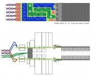
Do you see a problem if I make the -Ve and _Ve rails on separate pcb's joined by their earths using a solid metal block and then using this as the star gnd ?
(attached - pcb's mounted back to back, vertically allows vertical heatsink fins for the rectifier diodes)
Is the RC worth the trouble ?
Is LC even better ?
Do you see a problem if I make the -Ve and _Ve rails on separate pcb's joined by their earths using a solid metal block and then using this as the star gnd ?
(attached - pcb's mounted back to back, vertically allows vertical heatsink fins for the rectifier diodes)
Attachments
- Status
- This old topic is closed. If you want to reopen this topic, contact a moderator using the "Report Post" button.
- Home
- Amplifiers
- Solid State
- TGM Amplifier ?