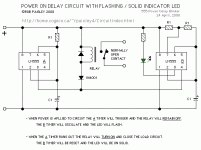
i have found out this schematic - it is one delay time to power the relay on after some time - but also has a flashing LED that stops flashing after the relay is turned on...
what i want to make is a TWO TIME DELAY (after one time runs out, first relay powers on and than after second time runs out, the second relay powers on) and the LED that will flash until the second time has run out and after that time it stays solid...
i have some trouble with understanding logic circuits. To old i guess.
thanks
Attachments
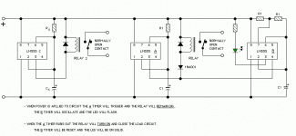
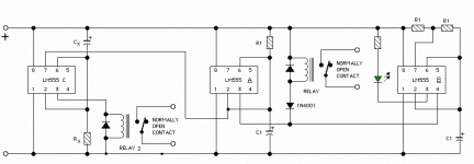
You can add a "c" timer, but you need the C timer to be the shorter time period timer.
Switch on system... after a short delay, timer C times out and switches its relay, but A is still 'counting', so the led still flashes.
Timer C will by electrically not connected to A or B, merely sharing the same power supply.
Construct timer C the same as timer A, but link the output pin of the 555 (pin 3 ) to the 'C' relay only - and not to any other 555. And compute the timing the same way as for timer A, but use a bigger capacitor, or smaller charging resistor.
Do you have the relevant formulae for 555 timing components?
steerpike - thank you for the interest in this thread. thank you very much.
yes - i need three NE555. A, B and C. From the schematic in the first post of this thread, A timer needs to have also his own relay, and the C timer needs to have his own also. So in fact i have two timers that will have theirs separate relays an one timer that will flash the LED until the timer A runs his time out. So, what you propose is to simply construct a timer C the same way as timer A (but with shorter time), and also to simply connect it to pin 3 of the timer A. Right?
The problem is, which pin of the timer C i should connect to the timer A - pin 4 or ????
That is what i am not sure about - I know that relay A is a timer and that i need 2 of them but how to connect them with the timer B to have everyhing running like i want it......
that is what i do not know. Formulas are also not a problem.
Thanks for any replies,
sunny
yes - i need three NE555. A, B and C. From the schematic in the first post of this thread, A timer needs to have also his own relay, and the C timer needs to have his own also. So in fact i have two timers that will have theirs separate relays an one timer that will flash the LED until the timer A runs his time out. So, what you propose is to simply construct a timer C the same way as timer A (but with shorter time), and also to simply connect it to pin 3 of the timer A. Right?
The problem is, which pin of the timer C i should connect to the timer A - pin 4 or ????
That is what i am not sure about - I know that relay A is a timer and that i need 2 of them but how to connect them with the timer B to have everyhing running like i want it......

that is what i do not know.
Thanks for any replies,
sunny
The picture should show it all. Timer C operates totally independantly of the other 2.
This MAY not suit your application - i don't know what it is - since a fault in the 'C' timer, would not stop timer A from switching. A will switch after its time period, whether C is working right or not.
If that is going to be risky, and if you need that A is allowed to switch ONLY if C has switched, and if C never switches, then A must be stopped from switching, that requres a little more complex wiring, but is still doable.
It is usual to put a 0.01uf capacitor from pin-5 to ground on the 555 chip, to make it less susceptible to noise.
Attachments
Mr.Steerpike - i have a question...
i have read somewhere that NE555 might turn on even if capacitor is not present - when resistor is going to the pin2 of the timer? i will post a schematic, in this post, where the capactior is added to prevent turning on...
The question is - timer A - could it turn on even if capacitor is not connected to ground (because of resistor going from psu to pin2)??
Yes! You are right! I should have looked at the 555 datasheet - and not tried to do this out of my head!
Your circuit maybe.pdf ought to work.
What I was trying to do was prevent C1 from charging until timer C had timed out, WITHOUT using any more components.
I have fixexed my diagram below to include a transistor.
But if you really want to do it with no extra components, I have another idea, shwn in next post (only one attachment per post it seems)
Attachments
Steerpike said:Yes! You are right! I should have looked at the 555 datasheet - and not tried to do this out of my head!
Your circuit maybe.pdf ought to work.
What I was trying to do was prevent C1 from charging until timer C had timed out, WITHOUT using any more components.
I have fixexed my diagram below to include a transistor.
But if you really want to do it with no extra components, I have another idea, shwn in next post (only one attachment per post it seems)
oh boy... i got something right
thanks - your circuit looks nice.
Steerpike said:with no extra components....
Steerpike - it seems to me that this schematic is the same as the one with one transistor... Maybe you did not want to attach this image but some other

i want to thank you for the effort - really - you are the only one that wanted to do some effort to help little old stupid me... thank you again.
Dang! I am doing some klutzy things today!
THIS is the picture I meant to upload.
On the first timer R and C change place, so the output on pin 3 starts off low, and after a time goes high.
This lets you use the internal 'discharge' transistor to discharge the timing capacitor of 555-B, instead of an external discharge transistor.
(Because the discharge transistor is conduts then the output is low, you have to swap the R and C.)
Attachments
- Status
- This old topic is closed. If you want to reopen this topic, contact a moderator using the "Report Post" button.
- Home
- Amplifiers
- Solid State
- NE555 two times delay


