Joshua_G
You are correct and that schematic is the one I copied over to this thread. The issue is that there are some discrepancies between the boards and that schematic, which is why Andrea's schematic differs from the one I posted.
So which, if either, is correct? I contend we won't know until one of us builds a working version and posts the canonical (i.e., reference) schematic with, of course, Steve's review.
What happened was that the first Krill 50 Steve published was before he knew he had those boards. Later on he corrected it few times, so that it will fit the boards and there is a last version by him.
It appears that the final Krill 50 should be the basis, into which additions and changes for the 100W should be added.
It appears that the final Krill 50 should be the basis, into which additions and changes for the 100W should be added.
First, I need to say I have a new E-mail address. If I havent already notified you by E-mail you can get it from my profile.
I am here today. The testing starts in the morning. I know I will be away at least half of tomorrow and all of Wednesday.
I am working on the schematics. I will post both the 50W and 100W versions. I will do two versions of each. One will match the boards I have and the other will show the improvements represented by the addition of the trim pots.
Andrea,
The 100W units were built with different transistors. The transistors used have been discontinued so I specified the newer ones that people could get. The specs on the outputs are very close. The TO220s were slightly different in that they had a higher current and dissipation rating.
I no longer have an original schematic with part values shown, so I am working from memory. I may be incorrect on the values for the current sources. They can be reduced from 10mA to 5mA with little effect on performance. The maximum output current will be limited to about 50A instead of 100A.
I only built two of the mono amps to confirm they were correct. The rest were built elsewhere. That was over 13 years ago and a lot has happened to me since then. I wish I could build up an test a pair of the amps now so I could catch these problems myself.
A number of builders, some working with my boards and some from their own boards, have E-mailed me to say they had successfully built and listened to the amps. I believe they all built the 50W units. It is possible that the reduced dissipation with the lower supply voltages accounts for their not encountering this problem.
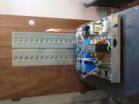
Here's my power amp prototyping board. Right now it's set-up for TO-3 output transistors but I can bolt an aluminum angle to the heatsinks for TO-3P's.
The big power transformer is 90VCT at 1.4 kW. The small transformer is a Signal split-bobbin transformer with a 120 VCT secondary at 0.85A. There are circuits for output fault sensing/speaker protection and soft-start.
The big power transformer is 90VCT at 1.4 kW. The small transformer is a Signal split-bobbin transformer with a 120 VCT secondary at 0.85A. There are circuits for output fault sensing/speaker protection and soft-start.
Attachments
Hi all,
I reduced the current to 6mA but things now are worse.
The BJTs run cooler but Q7 and Q10 don't develop enough voltage between their emitters (probably due to the lower current) to properly bias the diode string and the output devices.
Reducing R15 from 100k to 33k marginally helps but I'm still unable to set bias current higher than 10mA.
Will try adding a heatsink but I must confess I'm a bit puzzled.
Any suggestions?
Ciao
Andrea
R15 Should not need to be adjusted unless the supply voltages are changed. It sets the current for the diodes at about 1mA. This gives a voltage drop of 0.6V (approximately) for each diode. As the current increases, the voltage drop increases, up to a point. This will increase the current in the current sources.
At this point, I'm not sure what to suggest other than check your work. Make sure everything is where it is supposed to be and values are correct. Check solder connections.
I have had a report since my last post of another successful build. He was able to set the bias over 100mA and adjust it easily. Has anyone else encountered Andrea's problem?
Hi Steve,
I tried reducing R15 to increase current (and therefore voltage) acress the diodes. This has only a slight effect, just for testing purposes.
Heatsinking Q7 and Q10 (it was a pain to do since there is very little space) allows me to get to 60mA.
I checked my board and it looks fine....
Ciao
Andrea
I tried reducing R15 to increase current (and therefore voltage) acress the diodes. This has only a slight effect, just for testing purposes.
Heatsinking Q7 and Q10 (it was a pain to do since there is very little space) allows me to get to 60mA.
I checked my board and it looks fine....
Ciao
Andrea
Re: Transistor temperature dissipation, maximum power...
Carlos,
the 2W rating is for ambient temperature of 25°C.
This translates into a 62.5°C/W Rth J-A (junction-ambient)
Max power dissipation for the device is 20W with infinite heatsink.
This means 6.25 °C/W Rth J-C (junction/case) and is the rating you are talking about.
Non insulated TO220 devices have the same Rth J-A but lower Rth J-C , allowing for higher dissipation when heatsinked.
Ciao
Andrea
PS Any 100W builders around here?
destroyer X said:
is measured while the component is keept at 25 degrées celsius using a special cooling system.
Real life is not that way...so.... the 2 watts rating will not be correct unless the case is at 25 degrées celsius... as it is not.... it is not 2 watts too.
regards,
Carlos
Carlos,
the 2W rating is for ambient temperature of 25°C.
This translates into a 62.5°C/W Rth J-A (junction-ambient)
Max power dissipation for the device is 20W with infinite heatsink.
This means 6.25 °C/W Rth J-C (junction/case) and is the rating you are talking about.
Non insulated TO220 devices have the same Rth J-A but lower Rth J-C , allowing for higher dissipation when heatsinked.
Ciao
Andrea
PS Any 100W builders around here?
Hummmm... is this the construction thread or the "krill party"??
No party here.. not till the "deed is done".
Here is the PCB.. you can use any devices for OP or drivers,
to-126 or 220 (just "flip em' around") ECB/BCE.
Nifty SMD bias in 1 X1 " board with trimmer.
http://71.203.210.93/pdf1/Electronics/Projects/Audio_amp/Krill/
File is ... krill_pcb_artwork.zip (1.33meg)
ALL modifications are included BUT can be omitted if desired.
Schema explains options.
Any errors, please notify. (but I doubt it. )
OS
No party here.. not till the "deed is done".
Here is the PCB.. you can use any devices for OP or drivers,
to-126 or 220 (just "flip em' around") ECB/BCE.
Nifty SMD bias in 1 X1 " board with trimmer.
http://71.203.210.93/pdf1/Electronics/Projects/Audio_amp/Krill/
File is ... krill_pcb_artwork.zip (1.33meg)
ALL modifications are included BUT can be omitted if desired.
Schema explains options.
Any errors, please notify. (but I doubt it.
)OS
Attachments
ostripper said:Hummmm... is this the construction thread or the "krill party"??
No party here.. not till the "deed is done".
OS
Hi OS - I tried your site but can't connect at the moment - most likely being drained dry by others wanting to download your stuff.

The board looks GREAT!
 I'm assuming that the big caps and diodes for the PS are on a daughter board?
Ya wanna bring it to a "Krill Fest" should be be able to get one put together? I would love to get a chance to meet you and check out your gear.
BTW - have you fired this version up and did any listening test? Also - what VAS are you considering? hmmm this is getting a little OT for Andrea's thread - maybe this should be over at the "Krill" thread.
Hi Andrea,
Hi OS,
-Chris
That will be later for me. I am interested in the 100 watt version, I have enough 50 watt amps around here (SymAsym).PS Any 100W builders around here?
Hi OS,
Thank you sir! Your efforts are appreciated.Here is the PCB.. you can use any devices for OP or drivers, to-126 or 220 (just "flip em' around") ECB/BCE.
-Chris
By anatech -Thank you sir! Your efforts are appreciated
Whats up,chris.. You can use any of the to-3p or to247's
for op , 220uf or 470uf decoupling caps , LED or diode CCS,
decoupling AT CCS.
Just a "universal" OPS board ... I might even try a pair of
OPA445's to drive these.
Please don't bother with the large .BMP's , just the
krill_ops_artwork.zip ...everything is in there!!!
OS
Hi Terry,
Most products using a balanced input simply use an adapter type circuit. Not too many are balanced throughout. Often this just complicates the design.
Now, why do you want a balanced line in? Are your noise issues that bad? Anyway, try the INA134 or INA137 from Burr-Brown, now owned by TI. These have the gain setting resistors on board and laser trimmed. Otherwise it's too difficult to retain the CMRR that I suspect you are looking for.
Hi ostripper,
Yes, thank you. I downloaded them already from your site. Nifty site you have. Bare bones and efficient as a file repository. A really big help to those members who are looking for up to date information.
I guess you pretty much know I'll be using current sources for this, and the universal output stage is useful as well. I really liked the newer style output transistors you are laid out for. You could also still use TO-3s by running wire, which is normal when using that package to begin with.
-Chris
- Home
- Amplifiers
- Solid State
- Krill construction thread - 100W version