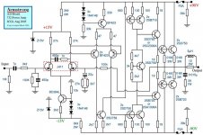
come across this schematic that looks a fairly simple and nice construction ....
the truth is that sudenlly i have the complete list of the original semiconductors available ( yeS !!!!) but what really troubles me is that from expirence it seems that rail voltage looks way higher than needed
also looking at this circuit notice that there is no VI limiters or any oher form of limiting and also heatsinks are notreally something huge ....
so my calculation say that this doesnt look safe ....
your opinion please ????
Attachments
yes.....
that is correct and thank you very much
but this is a factory made design called armstrong .... here is a link
http://www.audiomisc.co.uk/Armstrong/700/700page1.html
that is correct and thank you very much
but this is a factory made design called armstrong .... here is a link
http://www.audiomisc.co.uk/Armstrong/700/700page1.html
h_a said:15 V rails for the frontend? Difference shamelessly burned with a resistor?
Let's see you find (affordable) JFETs that can handle the 90 volt rails. With two differential stages, you can get away with running the first one off lower voltage - its no different than an op-amp front end.
A word of caution - there isn't any frequency compensation in this amp schematic. It will need the usual collector-base caps on both sides of the VAS and because of the extra front end stage, a lead compensation cap as well. An experienced builder will know how to calculate this (or at least tune it in experimentally).
Re: yes.....
The schematic given may be incomplete (ie, no compensation values, no SOA limiters, etc). It also looks like 'consumer grade' electronics to me. Two output pairs will do 8 ohms just fine if that's all you ever drive. Sony receiver/amps can't handle anything but 8 ohm loads, either.
sakis said:that is correct and thank you very much
but this is a factory made design called armstrong .... here is a link
http://www.audiomisc.co.uk/Armstrong/700/700page1.html
The schematic given may be incomplete (ie, no compensation values, no SOA limiters, etc). It also looks like 'consumer grade' electronics to me. Two output pairs will do 8 ohms just fine if that's all you ever drive. Sony receiver/amps can't handle anything but 8 ohm loads, either.
the Armstrong claims ONLY 200W for a BJT output stage from +-90Vdc.
The literature confirms 85Vpk output on music transients and also states that no current limiting nor protection is installed.
I suspect that a small transformer and low values of smoothing capacitance are being used to protect the output stage during abuse conditions.
Normally we'd expect 200W from +-60Vdc to +-65Vdc.
AndrewT said:the Armstrong claims ONLY 200W for a BJT output stage from +-90Vdc.
Gotta wonder if it will make point five past lightspeed (or the Kessel Run in sub-12 parsecs).

Let's see you find (affordable) JFETs that can handle the 90 volt rails.
Naah!
Much more elegant possibilities available than to roast a resistor. Like use a cascode and employ a nice series regulator for the frontend. Or use the resistor at the very least as part of a CRC filter.
Not that it's strictly needed, but hey, using a power resistor feels just primitive IMHO. Does not speak in favour of the design.
Missing compensation does not either
If I have to rework that circuit before building it, I can build something entirely different instead as well
Have fun, Hannes
Sometimes higher voltage rails are given to avoid hard clipping problems which I think is the case here, although the voltage needed be so high. Anyway if you looking for high voltage Jfets try these, they on par with the well known toshiba parts and in some respects even better. 2sk223.
Michael Chua said:90V rails, 200W rating = Dynamic Headroom.
Would be wise to double the outputs.
If it were one of those amps that can really put out 400Wx2/8R, and only claims 200 - so that they can claim 3dB headroom and doubling down to 4 ohms (and again at 2) it would have more than any two or four pairs of outputs per channel. More like 6, 8 or even 12 pairs.
jacco vermeulen said:~50A peak from a pair of Hitachi bipolar power transistors that can't according to their datasheet.
Woudn't be the first time.
Wowza, must have been some power amp.
Or they needed the smell of burnt carbon resistors to cover up what they were smoking in the engineering lab.
From NAD 2400
An externally hosted image should be here but it was not working when we last tested it.
thank you all
for your answers and information .....
i would have second thoughts on builting this thing even with a couple more sets of transistors since and since bias will have to be redesigned and of course VI limiters also ....
then just go for DIRTY HARRY BY FOTIOS and all will be just fine
thanks !!!!
for your answers and information .....
i would have second thoughts on builting this thing even with a couple more sets of transistors since and since bias will have to be redesigned and of course VI limiters also ....
then just go for DIRTY HARRY BY FOTIOS and all will be just fine
thanks !!!!
djk said:The NAD 2200 would bench at 360W/8R for about a half second (far longer than a musical transient).
If you drove it with a sinewave more than a second, it would shut down the ±93V rails, and just run on the ±60V rails (which is what the 100W long term rating was about).
This would describe a Class G amp http://en.wikipedia.org/wiki/Electronic_amplifier#Class_G_and_H
FWIW- The new generation of car decks use class H with an internal charge boost (external cap only) for up to 70V for short term.
The TDA1562 is a monolithic integrated 70 W/4 W
Bridge-Tied Load (BTL) class-H high efficiency power
amplifier in a 17 lead DIL-bent-SIL plastic power package
Different manufacturers reverse their descriptions of class G and class H.
I use the reference cited in the Wikipedia:
http://www.qscaudio.com/support/library/papers/amptalk.pdf
And Douglas Self:
To retain our sanity, I suggest following the above convention.
Early examples of class G:
http://www.google.com/patents?id=E2kCAAAAEBAJ&printsec=abstract&zoom=4&dq=3622899#PPA1,M1
http://www.google.com/patents?id=z-c2AAAAEBAJ&printsec=abstract&zoom=4&dq=3772606#PPA1,M1
god i hate nad amps
all..... but all of them ....
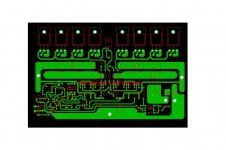
ok !!!! since i had a quiet time this afton i though about making a pcb with the above circuit but with plastic transistors and totally 8 transistors in the out for every board .....
anybody willing to try it is very welcome and i also have gerber export for it ....
please notice that this isa demo and it is possible that i ve made mistakes that i couldnt find with double checking !!!!!
there you go
all..... but all of them ....
ok !!!! since i had a quiet time this afton i though about making a pcb with the above circuit but with plastic transistors and totally 8 transistors in the out for every board .....
anybody willing to try it is very welcome and i also have gerber export for it ....
please notice that this isa demo and it is possible that i ve made mistakes that i couldnt find with double checking !!!!!
there you go
Attachments
- Status
- This old topic is closed. If you want to reopen this topic, contact a moderator using the "Report Post" button.
- Home
- Amplifiers
- Solid State
- 90+90 volt rails