Two general and basic questions about spring reverb units.
I am building a solid state guitar amp, and I bought a new Acutronics spring reverb unit.
First question. When I build the amp, where and how does one hook the reverb unit into the circuit? I assume somewhere in the preamp stage, but where exactly is the best place to put it? I’ve seen tube amp schematics that show various configurations, but I haven’t been able to put my hands on a solid state preamp that shows how to incorporate a reverb unit.
Second, when scope testing the unit hooked into a driver and recovery circuit, what kind of wave form should I see so I know that the reverb circuit it is doing what it is supposed to do? I breadboarded the driver and recovery circuits exactly as the Acutronics web site described, and hooked in the unit. I ran a sine wave through the circuit. The input and output wave forms looked exactly the same. Does that mean it’s not working? What does a ‘reverbed’ sine wave look like? I expected to see at least some disturbance of the wave, but it was reproduced almost exactly.
Try testing it with something other than a sine wave. The reverb tank can only delay the signal. If you take a single frequency sine wave, delay it, then add it back to the original, the output is just the same wave with the amplitude and phase changed.
A pulse signal should show the effect of the spring reverb.
A pulse signal should show the effect of the spring reverb.
Reverb
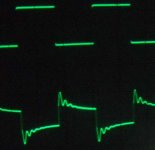
Many thanks, that worked. I tested it with a square wave and as I increased the reverb level, the square wave sloped down. Actually, the rise level increased, rang a bit, then sloped down. Interesting. I guess I forgot what I knew about sine waves - add two sine waves and you get a sine wave. I could attach a phot of the scope if anyone is interested.
As you would expect, the shape of the wave changed as the frequency varied. Hope this info helps someone else.
By the way, I have the reverb located between two op amps in a two-stage tone control for this particuylar test.
i would be very interested
i am mostly wondering what causes what you described as ringing ..... i ve seen it while repairing some transistor amps and i wasnt able to detect what causes that in some cases
thanks
TGRANT said:Many thanks, that worked. I tested it with a square wave and as I increased the reverb level, the square wave sloped down. Actually, the rise level increased, rang a bit, then sloped down. Interesting. I guess I forgot what I knew about sine waves - add two sine waves and you get a sine wave. I could attach a phot of the scope if anyone is interested.
As you would expect, the shape of the wave changed as the frequency varied. Hope this info helps someone else.
By the way, I have the reverb located between two op amps in a two-stage tone control for this particuylar test.
i am mostly wondering what causes what you described as ringing ..... i ve seen it while repairing some transistor amps and i wasnt able to detect what causes that in some cases
thanks
ringing
I’m not an expert, but some ringing is caused by resonance that is then dampened, for example the damped oscillation of an output transistor into a reactive load. I’m thinking that’s to some extent what a reverb circuit is. The springs are certainly reactive, but of course the load shouldn’t be (the load in my test circuit was a simple non-inverting op amp). I’d be curious if any of the more knowledgeable people have any comments on this one.
I’m not an expert, but some ringing is caused by resonance that is then dampened, for example the damped oscillation of an output transistor into a reactive load. I’m thinking that’s to some extent what a reverb circuit is. The springs are certainly reactive, but of course the load shouldn’t be (the load in my test circuit was a simple non-inverting op amp). I’d be curious if any of the more knowledgeable people have any comments on this one.
spring reverb
What determines the load impedence of the reverb circuit - the transformers, or the input impedence of the recovery circuit? The recovery circuit on the Acutronics web site appears to be a straight forward non-inverting op amp that should have a very high input impedence and should not be reactive. Is that correct reasoning?
What determines the load impedence of the reverb circuit - the transformers, or the input impedence of the recovery circuit? The recovery circuit on the Acutronics web site appears to be a straight forward non-inverting op amp that should have a very high input impedence and should not be reactive. Is that correct reasoning?
I think it is easier to think in "tube" terms. For example if you look at the replacement tanks for Fender amps you'll see the input is rated at 8 Ohms. Fender uses a small single ended output transformer with an 8 Ohm secondary to drive the tank or even a speaker. The xfmr on the output of the tank is low impedence that will drive the appropriate recovery circuit, tube or SS. So to answer your question the input/output transformers of the tank determine the circuitry.
Craig
Craig
That’s interesting. And it makes sense.
If anyone is interested, I have posted a photo of a square wave of the reverb circuit. The top is the square wave from the function generator, and the bottom is the wave after it has been blended with the output of the reverb recovery circuit.
T Grant
If anyone is interested, I have posted a photo of a square wave of the reverb circuit. The top is the square wave from the function generator, and the bottom is the wave after it has been blended with the output of the reverb recovery circuit.
T Grant
Attachments
- Status
- This old topic is closed. If you want to reopen this topic, contact a moderator using the "Report Post" button.
- Home
- Live Sound
- Instruments and Amps
- Spring Reverb Units